Electronics and Communication Engineering - Networks Analysis and Synthesis
Exercise : Networks Analysis and Synthesis - Section 1
- Networks Analysis and Synthesis - Section 14
- Networks Analysis and Synthesis - Section 27
- Networks Analysis and Synthesis - Section 26
- Networks Analysis and Synthesis - Section 25
- Networks Analysis and Synthesis - Section 24
- Networks Analysis and Synthesis - Section 23
- Networks Analysis and Synthesis - Section 22
- Networks Analysis and Synthesis - Section 21
- Networks Analysis and Synthesis - Section 20
- Networks Analysis and Synthesis - Section 19
- Networks Analysis and Synthesis - Section 18
- Networks Analysis and Synthesis - Section 17
- Networks Analysis and Synthesis - Section 16
- Networks Analysis and Synthesis - Section 15
- Networks Analysis and Synthesis - Section 1
- Networks Analysis and Synthesis - Section 13
- Networks Analysis and Synthesis - Section 12
- Networks Analysis and Synthesis - Section 11
- Networks Analysis and Synthesis - Section 10
- Networks Analysis and Synthesis - Section 9
- Networks Analysis and Synthesis - Section 8
- Networks Analysis and Synthesis - Section 7
- Networks Analysis and Synthesis - Section 6
- Networks Analysis and Synthesis - Section 5
- Networks Analysis and Synthesis - Section 4
- Networks Analysis and Synthesis - Section 3
- Networks Analysis and Synthesis - Section 2
26.
C = (2) (energy)/V2
Answer: Option
Explanation:

27.
A 3 phase balanced supply feeds 3 phase unbalanced load. Power supplied to the load can be measured by using
- 2 wattmeter
- one wattmeter
- 3 wattmeter
Answer: Option
Explanation:
A minimum of 2 wattmeters is required to measure 3 phase power. Of course power can be measured by putting one wattmeter in each phase.
28.
Which of the following is correct for a driving point functions?
Answer: Option
Explanation:
It is a necessary condition for response to be stable.
29.
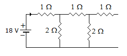
An infinite ladder is constructed with 1 Ω and 2 Ω resistors shown below.
Answer: Option
Explanation:
R = 1 + (2 || R)
 R = 2
R = 2
 .
.
30.
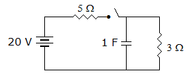
In the circuit of figure the voltage across capacitor when switch is closed at t = ∞ is
Answer: Option
Explanation:
Voltage across capacitor = voltage across 3Ω resistance = 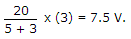
Quick links
Quantitative Aptitude
Verbal (English)
Reasoning
Programming
Interview
Placement Papers