Electronics and Communication Engineering - Networks Analysis and Synthesis
Exercise : Networks Analysis and Synthesis - Section 1
- Networks Analysis and Synthesis - Section 14
- Networks Analysis and Synthesis - Section 27
- Networks Analysis and Synthesis - Section 26
- Networks Analysis and Synthesis - Section 25
- Networks Analysis and Synthesis - Section 24
- Networks Analysis and Synthesis - Section 23
- Networks Analysis and Synthesis - Section 22
- Networks Analysis and Synthesis - Section 21
- Networks Analysis and Synthesis - Section 20
- Networks Analysis and Synthesis - Section 19
- Networks Analysis and Synthesis - Section 18
- Networks Analysis and Synthesis - Section 17
- Networks Analysis and Synthesis - Section 16
- Networks Analysis and Synthesis - Section 15
- Networks Analysis and Synthesis - Section 1
- Networks Analysis and Synthesis - Section 13
- Networks Analysis and Synthesis - Section 12
- Networks Analysis and Synthesis - Section 11
- Networks Analysis and Synthesis - Section 10
- Networks Analysis and Synthesis - Section 9
- Networks Analysis and Synthesis - Section 8
- Networks Analysis and Synthesis - Section 7
- Networks Analysis and Synthesis - Section 6
- Networks Analysis and Synthesis - Section 5
- Networks Analysis and Synthesis - Section 4
- Networks Analysis and Synthesis - Section 3
- Networks Analysis and Synthesis - Section 2
46.
A sinusoidal voltage has peak to peak value of 100 V. The rms value is
Answer: Option
Explanation:
Peak value = 50 V, rms value =  = 35.35 V.
47.
A capacitor is needed for an ac circuit of 230 V, 50 Hz the peak voltage rating of the capacitor should be
Answer: Option
Explanation:
Peak voltage rating = 2 (rms voltage rating).
48.
The current wave shape shown in figure (1) is applied to a circuit element. The voltage across the element is shown in figure (2). The element is
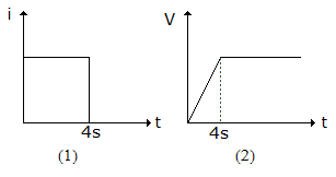
Answer: Option
Explanation:
When a current pulse is applied to a capacitor the voltage rises linearly and becomes constant at the end of pulse.
49.
In figure, the current supplied by battery immediately after switching on the circuit is
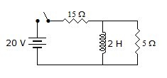
Answer: Option
Explanation:
At t = 0, inductance behaves as open circuit.
50.
RMS value of i(t) = 10[1 + sin (- t)] is
Answer: Option
Explanation:
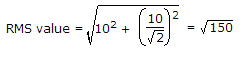 .
.
Quick links
Quantitative Aptitude
Verbal (English)
Reasoning
Programming
Interview
Placement Papers