Electronics and Communication Engineering - Networks Analysis and Synthesis
Exercise : Networks Analysis and Synthesis - Section 12
- Networks Analysis and Synthesis - Section 14
- Networks Analysis and Synthesis - Section 27
- Networks Analysis and Synthesis - Section 26
- Networks Analysis and Synthesis - Section 25
- Networks Analysis and Synthesis - Section 24
- Networks Analysis and Synthesis - Section 23
- Networks Analysis and Synthesis - Section 22
- Networks Analysis and Synthesis - Section 21
- Networks Analysis and Synthesis - Section 20
- Networks Analysis and Synthesis - Section 19
- Networks Analysis and Synthesis - Section 18
- Networks Analysis and Synthesis - Section 17
- Networks Analysis and Synthesis - Section 16
- Networks Analysis and Synthesis - Section 15
- Networks Analysis and Synthesis - Section 1
- Networks Analysis and Synthesis - Section 13
- Networks Analysis and Synthesis - Section 12
- Networks Analysis and Synthesis - Section 11
- Networks Analysis and Synthesis - Section 10
- Networks Analysis and Synthesis - Section 9
- Networks Analysis and Synthesis - Section 8
- Networks Analysis and Synthesis - Section 7
- Networks Analysis and Synthesis - Section 6
- Networks Analysis and Synthesis - Section 5
- Networks Analysis and Synthesis - Section 4
- Networks Analysis and Synthesis - Section 3
- Networks Analysis and Synthesis - Section 2
21.
A two branch parallel tuned circuit has a coil of resistance 100 Ω and inductance 0.005 H in one branch and 10 nF capacitor in the second branch. At resonance frequency, the dynamic resistance is
Answer: Option
Explanation:
Dynamic resistance = 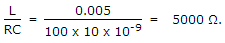
22.
If each branch of a Delta circuit has impedance 3 Z then each branch of the equivalent Y circuit has impedance.
Answer: Option
Explanation:
ZΔ = 3 Zy  Zy =
Zy = 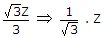 .
.
23.
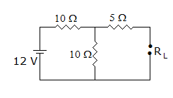
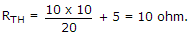
In the circuit of figure, Thevenin's resistance is 10 Ω
Answer: Option
Explanation:
24.
An RLC series circuit has R = 1 Ω, L = 1 H, C = 1 F. The damping ratio is
Answer: Option
Explanation:
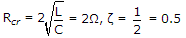 .
.
25.
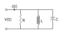
The circuit shown in the figure, with R = 1/3 Ω, L = 1/4H, C = 3F has input voltage v(t) = sin2t. The resulting current i(t) is
Answer: Option
Explanation:
i(t) = iR(t) + iL(t) + iC(t)
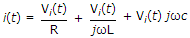
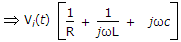 .
.
Quick links
Quantitative Aptitude
Verbal (English)
Reasoning
Programming
Interview
Placement Papers