Electronics and Communication Engineering - Networks Analysis and Synthesis - Discussion
Discussion Forum : Networks Analysis and Synthesis - Section 12 (Q.No. 25)
25.
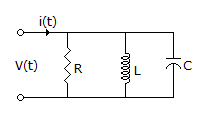
The circuit shown in the figure, with R = 1/3 Ω, L = 1/4H, C = 3F has input voltage v(t) = sin2t. The resulting current i(t) is
Answer: Option
Explanation:
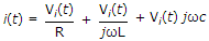
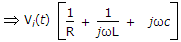
i(t) = iR(t) + iL(t) + iC(t)
 .
.
Discussion:
Be the first person to comment on this question !
Post your comments here:
Quick links
Quantitative Aptitude
Verbal (English)
Reasoning
Programming
Interview
Placement Papers