Electronics and Communication Engineering - Exam Questions Papers
Exercise : Exam Questions Papers - Exam Paper 8
- Exam Questions Papers - Exam Paper 12
- Exam Questions Papers - Exam Paper 22
- Exam Questions Papers - Exam Paper 21
- Exam Questions Papers - Exam Paper 20
- Exam Questions Papers - Exam Paper 19
- Exam Questions Papers - Exam Paper 18
- Exam Questions Papers - Exam Paper 17
- Exam Questions Papers - Exam Paper 16
- Exam Questions Papers - Exam Paper 15
- Exam Questions Papers - Exam Paper 14
- Exam Questions Papers - Exam Paper 13
- Exam Questions Papers - Exam Paper 1
- Exam Questions Papers - Exam Paper 11
- Exam Questions Papers - Exam Paper 10
- Exam Questions Papers - Exam Paper 9
- Exam Questions Papers - Exam Paper 8
- Exam Questions Papers - Exam Paper 7
- Exam Questions Papers - Exam Paper 6
- Exam Questions Papers - Exam Paper 5
- Exam Questions Papers - Exam Paper 4
- Exam Questions Papers - Exam Paper 3
- Exam Questions Papers - Exam Paper 2
31.
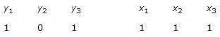
The logic circuit given below converts a binary code y1 y2, y3 into
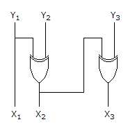
Answer: Option
Explanation:
Let y1 = 1, y2 = 0, y3 = 1
then x1 = 1
x2 = y1 ⊕ y2 ⇒ 1 ⊕ 0 ⇒ 1
x3 = x2 ⊕ y3 = 1 ⊕ 0 = 1
which is gray code conversion.
32.
A system described by the following differential equation 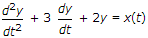 is initially at rest. For input x(t) - 2u(t), the output y(t) is :
is initially at rest. For input x(t) - 2u(t), the output y(t) is :Answer: Option
Explanation:
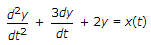
Taking L.T.
s2y(s) + 3sy(s) + 2y(s) = x(s)
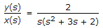
I.L.T = (1 - 2e-t + e-2t)U(t).
33.
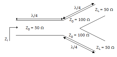
A transmission line terminates in two branches, each of length λ/4, as shown. The branches are terminated by 50Ω loads. The lines are lossless and have the characteristics impedances shown. Determine the impedance Z1 as seen by the source
Answer: Option
Explanation:
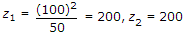

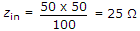 .
.
34.
The Nyquist plot of
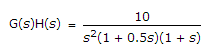
Answer: Option
Explanation:
35.
The counter shown in figure is built using 4 negative edge triggered toggle FFs. The FFs can be set synchronously when R = 0. The combinational logic required to realize a modulo 13 counter is
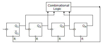
Answer: Option
Explanation:
According to figure, output of combinational logic is applied to R of all FF
N = 13 = (1101)2
The logic required is Q4 Q3 Q2 Q1 The gate used is a NAND.
Y = Q4 + Q3 + Q2 + Q1 .
Quick links
Quantitative Aptitude
Verbal (English)
Reasoning
Programming
Interview
Placement Papers