Electronics and Communication Engineering - Exam Questions Papers - Discussion
Discussion Forum : Exam Questions Papers - Exam Paper 8 (Q.No. 35)
35.
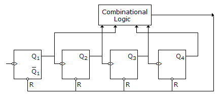
The counter shown in figure is built using 4 negative edge triggered toggle FFs. The FFs can be set synchronously when R = 0. The combinational logic required to realize a modulo 13 counter is
Answer: Option
Explanation:
According to figure, output of combinational logic is applied to R of all FF
N = 13 = (1101)2
The logic required is Q4 Q3 Q2 Q1 The gate used is a NAND.
Y = Q4 + Q3 + Q2 + Q1 .
Discussion:
1 comments Page 1 of 1.
Pranati Sharma said:
9 years ago
Answer must be an option A.
Post your comments here:
Quick links
Quantitative Aptitude
Verbal (English)
Reasoning
Programming
Interview
Placement Papers