Electronics and Communication Engineering - Digital Electronics
Exercise : Digital Electronics - Section 1
- Digital Electronics - Section 13
- Digital Electronics - Section 24
- Digital Electronics - Section 23
- Digital Electronics - Section 22
- Digital Electronics - Section 21
- Digital Electronics - Section 20
- Digital Electronics - Section 19
- Digital Electronics - Section 18
- Digital Electronics - Section 17
- Digital Electronics - Section 16
- Digital Electronics - Section 15
- Digital Electronics - Section 14
- Digital Electronics - Section 1
- Digital Electronics - Section 12
- Digital Electronics - Section 11
- Digital Electronics - Section 10
- Digital Electronics - Section 9
- Digital Electronics - Section 8
- Digital Electronics - Section 7
- Digital Electronics - Section 6
- Digital Electronics - Section 5
- Digital Electronics - Section 4
- Digital Electronics - Section 3
- Digital Electronics - Section 2
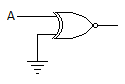
11.
For the gate in the given figure the output will be
Answer: Option
Explanation:
If A = 0, Y = 1 and A = 1, Y = 0 Therefore Y = A.
12.
In the expression A + BC, the total number of minterms will be
Answer: Option
Explanation:
The min terms are ABC + ABC + AB C + ABC + ABC.
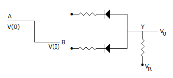
13.
The circuit in the given figure is
Answer: Option
Explanation:
Since V(I) is lower state than V(0) it is a negative logic circuit. Since diodes are in reversed parallel, it is an AND gate.
Note: In Boolean algebra it is recognized that a positive logic OR is a negative logic AND. Similarly a positive logic AND is a negative logic OR.
14.
Which of the following is non-saturating?
Answer: Option
Explanation:
Since it is non-saturating, ECL has low propagation delay.
15.
The number of digits in octal system is
Answer: Option
Explanation:
The octal system has 8 digits 0 to 7.
Quick links
Quantitative Aptitude
Verbal (English)
Reasoning
Programming
Interview
Placement Papers