Online Electrical Engineering Test - Electrical Engineering Test 10
Instruction:
- This is a FREE online test. Beware of scammers who ask for money to attend this test.
- Total number of questions: 20.
- Time allotted: 30 minutes.
- Each question carries 1 mark; there are no negative marks.
- DO NOT refresh the page.
- All the best!
Marks : 2/20
Total number of questions
20
Number of answered questions
0
Number of unanswered questions
20
Test Review : View answers and explanation for this test.
1.
Free electrons make current possible.
Your Answer: Option
(Not Answered)
Correct Answer: Option
Discuss about this problem : Discuss in Forum
Learn more problems on : Voltage, Current and Resistance
2.
If 750 µA is flowing through 11 k of resistance, what is the voltage drop across the resistor?
of resistance, what is the voltage drop across the resistor?Your Answer: Option
(Not Answered)
Correct Answer: Option
Discuss about this problem : Discuss in Forum
Learn more problems on : Ohm's Law
3.
At the end of a 14 day period, your utility bill shows that you have used 18 kWh. What is your average daily power?
Your Answer: Option
(Not Answered)
Correct Answer: Option
Discuss about this problem : Discuss in Forum
Learn more problems on : Energy and Power
4.
A half-watt is equal to how many milliwatts?
Your Answer: Option
(Not Answered)
Correct Answer: Option
Discuss about this problem : Discuss in Forum
Learn more problems on : Energy and Power
5.
Series aiding is a term sometimes used to describe voltage sources of the same polarity in series.
Your Answer: Option
(Not Answered)
Correct Answer: Option
Discuss about this problem : Discuss in Forum
Learn more problems on : Series Circuits
6.
If there are a total of 120 mA into a parallel circuit consisting of three branches, and two of the branch currents are 40 mA and 10 mA, the third branch current is
Your Answer: Option
(Not Answered)
Correct Answer: Option
Discuss about this problem : Discuss in Forum
Learn more problems on : Parallel Circuits
7.
In a parallel circuit, the branch with the lowest resistance has the most current.
Your Answer: Option
(Not Answered)
Correct Answer: Option
Discuss about this problem : Discuss in Forum
Learn more problems on : Parallel Circuits
8.
What is the Thevenin equivalent (VTH and RTH) for the circuit given?
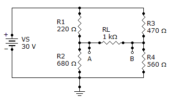
6.4 V, 422
6.4 V, 560
6.4 V, 680
30 V, 422
Your Answer: Option
(Not Answered)
Correct Answer: Option
Discuss about this problem : Discuss in Forum
Learn more problems on : Circuit Theorems and Conversions
9.
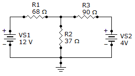
Find branch current IR2.
Your Answer: Option
(Not Answered)
Correct Answer: Option
Discuss about this problem : Discuss in Forum
Learn more problems on : Branch, Loop and Node Analyses
10.
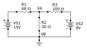
What is the current through R2?
Your Answer: Option
(Not Answered)
Correct Answer: Option
Discuss about this problem : Discuss in Forum
Learn more problems on : Branch, Loop and Node Analyses
11.
Third-order determinants are evaluated by the expansion method or by the cofactor method.
Your Answer: Option
(Not Answered)
Correct Answer: Option
Discuss about this problem : Discuss in Forum
Learn more problems on : Branch, Loop and Node Analyses
12.
A 2  F, a 4 F, and a 10 F capacitor are connected in series. The total capacitance is less than
F, a 4 F, and a 10 F capacitor are connected in series. The total capacitance is less than2 F
F4 F
F10 F
F1.5 F
FYour Answer: Option
(Not Answered)
Correct Answer: Option
Discuss about this problem : Discuss in Forum
Learn more problems on : Capacitors
13.
Five time constants are required for a capacitor to charge fully or discharge fully.
Your Answer: Option
(Not Answered)
Correct Answer: Option
Discuss about this problem : Discuss in Forum
Learn more problems on : Capacitors
14.
In an RL circuit, the impedance is determined by both the resistance and the inductive reactance combined.
Your Answer: Option
(Not Answered)
Correct Answer: Option
Discuss about this problem : Discuss in Forum
Learn more problems on : RL Circuits
15.
A certain series RLC circuit with a 200 Hz, 15 V ac source has the following values: R = 12 , C = 80 F, and L = 10 mH. The total impedance, expressed in polar form, is
, C = 80 F, and L = 10 mH. The total impedance, expressed in polar form, is12.28 12.34°
12.34° 12.5712.34°
12.34° 9.9512.34°
12.34° 12.6212.34°
12.34° Your Answer: Option
(Not Answered)
Correct Answer: Option
Discuss about this problem : Discuss in Forum
Learn more problems on : RLC Circuits and Resonance
16.
A 10 resistor, a 90 mH coil, and a 0.015 F capacitor are in series across an ac source. The impedance magnitude at 1,200 Hz below fr is
resistor, a 90 mH coil, and a 0.015 F capacitor are in series across an ac source. The impedance magnitude at 1,200 Hz below fr is1,616
161
3,387
1,771
Your Answer: Option
(Not Answered)
Correct Answer: Option
Discuss about this problem : Discuss in Forum
Learn more problems on : RLC Circuits and Resonance
17.
Referring to Problem 18, what is the bandwidth of the filter?
Your Answer: Option
(Not Answered)
Correct Answer: Option
Discuss about this problem : Discuss in Forum
Learn more problems on : Passive Filters
18.
If the RC time constant of an integrator is increased, as the time constant is increased
Your Answer: Option
(Not Answered)
Correct Answer: Option
Discuss about this problem : Discuss in Forum
Learn more problems on : Time Response of Reactive Circuits
19.
In an RC differentiator, the sum of the capacitor voltage and the resistor voltage at any instant
Your Answer: Option
(Not Answered)
Correct Answer: Option
Discuss about this problem : Discuss in Forum
Learn more problems on : Time Response of Reactive Circuits
20.
In an RL integrating circuit, the output voltage is taken across the inductor.
Your Answer: Option
(Not Answered)
Correct Answer: Option
Discuss about this problem : Discuss in Forum
Learn more problems on : Time Response of Reactive Circuits
*** END OF THE TEST ***
Time Left: 00:29:56
Post your test result / feedback here:
Quick links
Quantitative Aptitude
Verbal (English)
Reasoning
Programming
Interview
Placement Papers