Electronics and Communication Engineering - Exam Questions Papers
Exercise : Exam Questions Papers - Exam Paper 5
- Exam Questions Papers - Exam Paper 12
- Exam Questions Papers - Exam Paper 22
- Exam Questions Papers - Exam Paper 21
- Exam Questions Papers - Exam Paper 20
- Exam Questions Papers - Exam Paper 19
- Exam Questions Papers - Exam Paper 18
- Exam Questions Papers - Exam Paper 17
- Exam Questions Papers - Exam Paper 16
- Exam Questions Papers - Exam Paper 15
- Exam Questions Papers - Exam Paper 14
- Exam Questions Papers - Exam Paper 13
- Exam Questions Papers - Exam Paper 1
- Exam Questions Papers - Exam Paper 11
- Exam Questions Papers - Exam Paper 10
- Exam Questions Papers - Exam Paper 9
- Exam Questions Papers - Exam Paper 8
- Exam Questions Papers - Exam Paper 7
- Exam Questions Papers - Exam Paper 6
- Exam Questions Papers - Exam Paper 5
- Exam Questions Papers - Exam Paper 4
- Exam Questions Papers - Exam Paper 3
- Exam Questions Papers - Exam Paper 2
46.
The polar plot for positive frequencies is shown below. The gain margin is
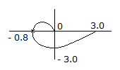
Answer: Option
Explanation:
47.
Input and output impedance with feedback for voltage series feedback having A = -200, R1 = 10 kΩ, R0 = 50 kΩ and feedback factor β = -0.2 will be
Answer: Option
Explanation:
In voltage series feedback output impedance decreases, input impedance increases,
 , Rif = Ri(1 + Aβ).
48.
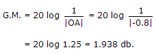
Z = __________
Answer: Option
Explanation:
Output of first MUX = A(B + C)
Output of second MUX = C D + A B).
49.
An FM transmitter delivers 80W to a load of 30 W when no modulation is present. The carrier is now frequency modulated by a single sinusoidal signal and the peak frequency deviation is so adjusted to make the amplitude of the second sideband is zero in the given output.
J0(0, 0) = 1,
J0(2, 4) = 0,
J0(3.8) = - 0.4,
J0(5.1)= - 0.1
J1(2, 4) = 0.52,
J1((3.8) = 0,
J1(5.1) = - 0.33,
J2(2.4) = 0.1
J2(3.8)= 0.41,
J2(5.1) = 0
The power in all the remaining sidebands is :
J0(0, 0) = 1,
J0(2, 4) = 0,
J0(3.8) = - 0.4,
J0(5.1)= - 0.1
J1(2, 4) = 0.52,
J1((3.8) = 0,
J1(5.1) = - 0.33,
J2(2.4) = 0.1
J2(3.8)= 0.41,
J2(5.1) = 0
The power in all the remaining sidebands is :
Answer: Option
Explanation:
Total power of the FM transmitter = 80 W to a load of 50 W
second side band amplitude = J2(β) = 0
∴ β = 5.1
Average Power = (J0(β))2 x 100 = (0.16)2 x 100 = 2.56 W
Power in all remaining = 80 - 2.56 = 77.44 .
50.
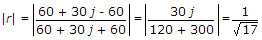
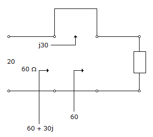
In the circuit shown, all the transmission line sections are lossless. The Voltage Standing Wave Ration (VSWR) on the 60W line is
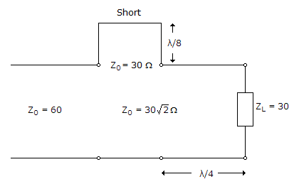
Answer: Option
Explanation:

Quick links
Quantitative Aptitude
Verbal (English)
Reasoning
Programming
Interview
Placement Papers