Electronics and Communication Engineering - Exam Questions Papers
Exercise : Exam Questions Papers - Exam Paper 3
- Exam Questions Papers - Exam Paper 12
- Exam Questions Papers - Exam Paper 22
- Exam Questions Papers - Exam Paper 21
- Exam Questions Papers - Exam Paper 20
- Exam Questions Papers - Exam Paper 19
- Exam Questions Papers - Exam Paper 18
- Exam Questions Papers - Exam Paper 17
- Exam Questions Papers - Exam Paper 16
- Exam Questions Papers - Exam Paper 15
- Exam Questions Papers - Exam Paper 14
- Exam Questions Papers - Exam Paper 13
- Exam Questions Papers - Exam Paper 1
- Exam Questions Papers - Exam Paper 11
- Exam Questions Papers - Exam Paper 10
- Exam Questions Papers - Exam Paper 9
- Exam Questions Papers - Exam Paper 8
- Exam Questions Papers - Exam Paper 7
- Exam Questions Papers - Exam Paper 6
- Exam Questions Papers - Exam Paper 5
- Exam Questions Papers - Exam Paper 4
- Exam Questions Papers - Exam Paper 3
- Exam Questions Papers - Exam Paper 2
31.
The common emitter model is shown below:
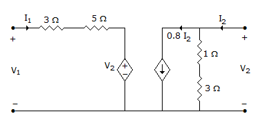
The h-parameter of this model are:
The h-parameter of this model are:


Answer: Option
Explanation:
h parameter 
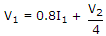
V1 = (3 + 5)I1 + V2
 .
.
32.
In the following limiter circuit, an input voltage V1 = 10 sin 100pt applied. Assume that the diode drop is 0.7 V when it is forward biased. The zener breakdown voltage is 6.8 V
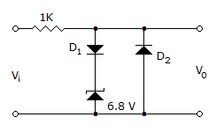
The maximum and minimum values of the output voltage respectively are
The maximum and minimum values of the output voltage respectively are
Answer: Option
Explanation:
During +ve part of Vi
D1 will be forward biased
Zener diode is reverse biased
Thus net voltage = 6.8 + 0.7 = 4.5 V
During -ve part of Vi
D2 will be forward biased
D1 will be reversed biased
Thus net voltage = -0.7 V .
33.
Four signals
m1 = cos (ω0t), m2(t) = cos (ω0t), m3(t) = 2 cos (ω0t) and m4(t) = cos (4 ω0t) are multiplexed by Time Division Multiplexing system. The commutator speed in rps is
m1 = cos (ω0t), m2(t) =
cos (ω0t), m3(t) = 2 cos (ω0t) and m4(t) = cos (4 ω0t) are multiplexed by Time Division Multiplexing system. The commutator speed in rps isAnswer: Option
Explanation:
Apply Nyquist criteria.
Maximum angular speed is 4ω0
Thus commutator speed must be 2 x 4ω2 = 8ω0 .
34.
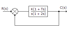
The feedback control system shown in figure is stable for what values of K and T?
Answer: Option
Explanation:
Apply Routh Hurwitz criteria.
35.
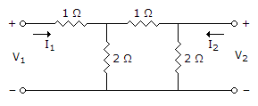
Find z parameters for the following network


Answer: Option
Explanation:
Use Mesh analysis
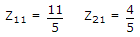
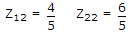
z parameters are given by,
V1 = Z11I1 + Z12I2 ...(a)
V2 = Z21I1 + Z22I2 ...(b)
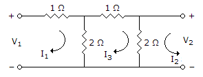
Apply KVL to mesh 1
V1 = 3I1 - 2I3 ...(i)
Apply KVL to mesh 2
V2 = 2I2 + 2I3 ...(ii)
Apply KVL to mesh 3
5I3 + 2I2 -2I1 =0 ...(iii)
5I3 = 2I1 - 2I2

Put I3 in eq. (i)
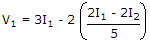
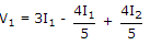
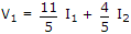 ...(iv)
Put in (ii)
Similarly, 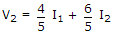 ...(v)
Compare equation (iv) to (a) and equation (v) to (b)
∴ 
 .
.
Quick links
Quantitative Aptitude
Verbal (English)
Reasoning
Programming
Interview
Placement Papers