Electronics and Communication Engineering - Digital Electronics
Exercise : Digital Electronics - Section 7
- Digital Electronics - Section 13
- Digital Electronics - Section 24
- Digital Electronics - Section 23
- Digital Electronics - Section 22
- Digital Electronics - Section 21
- Digital Electronics - Section 20
- Digital Electronics - Section 19
- Digital Electronics - Section 18
- Digital Electronics - Section 17
- Digital Electronics - Section 16
- Digital Electronics - Section 15
- Digital Electronics - Section 14
- Digital Electronics - Section 1
- Digital Electronics - Section 12
- Digital Electronics - Section 11
- Digital Electronics - Section 10
- Digital Electronics - Section 9
- Digital Electronics - Section 8
- Digital Electronics - Section 7
- Digital Electronics - Section 6
- Digital Electronics - Section 5
- Digital Electronics - Section 4
- Digital Electronics - Section 3
- Digital Electronics - Section 2
26.
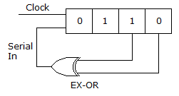
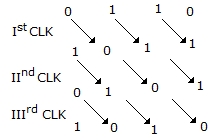
In following figure, the initial contents of the 4-bit serial in parallel out, right shift, shift register as shown in figure are 0110. After 3 clock pulses the contents of the shift register will be
Answer: Option
Explanation:
27.
For the logic circuit of the given figure, the minimized expression is
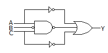

Y = A + B + C
Y = A + B
Y = ABC
Answer: Option
Explanation:
 + A + C = A + B + C + A + C = A + C + B
=
28.
Binary multiplication can be done by repeated addition.
29.
Assertion (A): In totem pole output the output impedance is low.
Reason (R): TTL gate with active pull up should not be used in wired AND connection.
30.
A 4 bit synchronous counter uses flip flops with a delay time of 15 ns each. The time required for change of state is
Answer: Option
Explanation:
In a synchronous counter clock input is applied to all flip flops simultaneously. Hence total delay time is 15 ns.
Quick links
Quantitative Aptitude
Verbal (English)
Reasoning
Programming
Interview
Placement Papers