Electronics and Communication Engineering - Digital Electronics
Exercise : Digital Electronics - Section 5
- Digital Electronics - Section 13
- Digital Electronics - Section 24
- Digital Electronics - Section 23
- Digital Electronics - Section 22
- Digital Electronics - Section 21
- Digital Electronics - Section 20
- Digital Electronics - Section 19
- Digital Electronics - Section 18
- Digital Electronics - Section 17
- Digital Electronics - Section 16
- Digital Electronics - Section 15
- Digital Electronics - Section 14
- Digital Electronics - Section 1
- Digital Electronics - Section 12
- Digital Electronics - Section 11
- Digital Electronics - Section 10
- Digital Electronics - Section 9
- Digital Electronics - Section 8
- Digital Electronics - Section 7
- Digital Electronics - Section 6
- Digital Electronics - Section 5
- Digital Electronics - Section 4
- Digital Electronics - Section 3
- Digital Electronics - Section 2
36.
Logic analyser is
Answer: Option
Explanation:
It is a multichannel oscilloscope.
37.
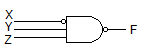
The minimized version of logic circuit in the given figure is
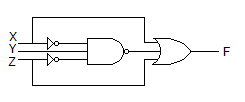
Answer: Option
Explanation:
The Boolean equation is  The circuit in the given figure
  gives
gives 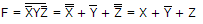 .
.
38.
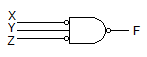
In the given figure shows a negative logic AND gate. If positive logic is used this gate is equivalent to

Answer: Option
Explanation:
Y = A B = A + B .
39.
The function Y = A B C + AB C + A B C + A BC is to be realized using discrete gates. The inputs available are A, B, C. We need a total of
Answer: Option
Explanation:
Three NOT gates, four AND gates and one OR gate, i.e., total of 8 gates.
40.
A 10 bit D/A converter gives a maximum output of 10.23 V. The resolution is
Answer: Option
Explanation:
Resolution =  V or 10 mV.
Quick links
Quantitative Aptitude
Verbal (English)
Reasoning
Programming
Interview
Placement Papers