Online Electrical Engineering Test - Electrical Engineering Test 4
Instruction:
- This is a FREE online test. Beware of scammers who ask for money to attend this test.
- Total number of questions: 20.
- Time allotted: 30 minutes.
- Each question carries 1 mark; there are no negative marks.
- DO NOT refresh the page.
- All the best!
Marks : 2/20
Total number of questions
20
Number of answered questions
0
Number of unanswered questions
20
Test Review : View answers and explanation for this test.
1.
When these numbers are multiplied, (6 × 10³) (5 × 10⁵), the result is
Your Answer: Option
(Not Answered)
Correct Answer: Option
Discuss about this problem : Discuss in Forum
Learn more problems on : Quantities and Units
2.
A circuit breaker is a
Your Answer: Option
(Not Answered)
Correct Answer: Option
Discuss about this problem : Discuss in Forum
Learn more problems on : Voltage, Current and Resistance
3.
A material that does not allow current under normal conditions is a(n)
Your Answer: Option
(Not Answered)
Correct Answer: Option
Discuss about this problem : Discuss in Forum
Learn more problems on : Voltage, Current and Resistance
4.
A current of 200 µA through a 6.8 k resistor produces a voltage drop of
resistor produces a voltage drop ofYour Answer: Option
(Not Answered)
Correct Answer: Option
Discuss about this problem : Discuss in Forum
Learn more problems on : Ohm's Law
5.
A 6 V battery is connected to a 300 load. Under these conditions, it is rated at 40 Ah. How long can it supply current to the load?
load. Under these conditions, it is rated at 40 Ah. How long can it supply current to the load?Your Answer: Option
(Not Answered)
Correct Answer: Option
Discuss about this problem : Discuss in Forum
Learn more problems on : Energy and Power
6.
A 68 resistor is connected across the terminals of a 3 V battery. The power dissipation of the resistor is
resistor is connected across the terminals of a 3 V battery. The power dissipation of the resistor isYour Answer: Option
(Not Answered)
Correct Answer: Option
Discuss about this problem : Discuss in Forum
Learn more problems on : Energy and Power
7.
The unit for reluctance is
Your Answer: Option
(Not Answered)
Correct Answer: Option
Discuss about this problem : Discuss in Forum
Learn more problems on : Magnetism and Electromagnetism
8.
The conductive loop on the rotor of a simple two-pole, single-phase generator rotates at a rate of 400 rps. The frequency of the induced output voltage is
Your Answer: Option
(Not Answered)
Correct Answer: Option
Discuss about this problem : Discuss in Forum
Learn more problems on : Alternating Current and Voltage
9.
In Question 6, the capacitor will reach full charge in a time equal to approximately
Your Answer: Option
(Not Answered)
Correct Answer: Option
Discuss about this problem : Discuss in Forum
Learn more problems on : Capacitors
10.
A capacitor and a resistor are connected in series to a sine wave generator. The frequency is set so that the capacitive reactance is equal to the resistance and, thus, an equal amount of voltage appears across each component. If the frequency is increased
Your Answer: Option
(Not Answered)
Correct Answer: Option
Discuss about this problem : Discuss in Forum
Learn more problems on : Capacitors
11.
When the current through an inductor decreases, the amount of energy stored in the electromagnetic field
Your Answer: Option
(Not Answered)
Correct Answer: Option
Discuss about this problem : Discuss in Forum
Learn more problems on : Inductors
12.
How many primary volts must be applied to a transformer with a turns ratio of 0.1 to obtain a secondary voltage of 9 V?
Your Answer: Option
(Not Answered)
Correct Answer: Option
Explanation:
We know that, V2/V1 = N2/N1.
Given V2 = 9v, N2/N1 = 0.1
Therefore, 9v/V1 = 0.1
V1 = 9v/0.1 = 90v.
For more detail: Step Down Transformer - Circuit with Simulation.
Discuss about this problem : Discuss in Forum
Learn more problems on : Transformers
13.
Referring to Problem 21, what is the phase angle for the circuit?
Your Answer: Option
(Not Answered)
Correct Answer: Option
Discuss about this problem : Discuss in Forum
Learn more problems on : RC Circuits
14.
A 470 resistor and a 0.2  F capacitor are in parallel across a 2.5 kHz ac source. The admittance, Y, in rectangular form, is
resistor and a 0.2 F capacitor are in parallel across a 2.5 kHz ac source. The admittance, Y, in rectangular form, is212
2.12 mS + j3.14 mS
3.14 mS + j2.12 mS
318.3
Your Answer: Option
(Not Answered)
Correct Answer: Option
Discuss about this problem : Discuss in Forum
Learn more problems on : RC Circuits
15.
The polar form of a complex number consists of a real part and a j part.
Your Answer: Option
(Not Answered)
Correct Answer: Option
Discuss about this problem : Discuss in Forum
Learn more problems on : RC Circuits
16.
A 470 resistor and a coil with 125 inductive reactance are in parallel. Both components are across a 15 V ac voltage source. Current through the inductor is
resistor and a coil with 125 inductive reactance are in parallel. Both components are across a 15 V ac voltage source. Current through the inductor isYour Answer: Option
(Not Answered)
Correct Answer: Option
Discuss about this problem : Discuss in Forum
Learn more problems on : RL Circuits
17.
The power factor indicates how much of the apparent power is reactive power.
Your Answer: Option
(Not Answered)
Correct Answer: Option
Discuss about this problem : Discuss in Forum
Learn more problems on : RL Circuits
18.
Referring to Problem 12, the voltage across the capacitor is
Your Answer: Option
(Not Answered)
Correct Answer: Option
Discuss about this problem : Discuss in Forum
Learn more problems on : RLC Circuits and Resonance
19.
Referring this circuit, determine the maximum output voltage when a single pulse is applied as shown. The total resistance is 60 .
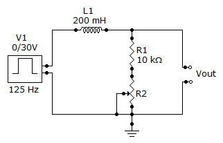
.
Your Answer: Option
(Not Answered)
Correct Answer: Option
Discuss about this problem : Discuss in Forum
Learn more problems on : Time Response of Reactive Circuits
20.
Referring to Problem 3, power consumption is
Your Answer: Option
(Not Answered)
Correct Answer: Option
Discuss about this problem : Discuss in Forum
Learn more problems on : Three-Phase Systems in Power Applications
*** END OF THE TEST ***
Time Left: 00:29:56
Post your test result / feedback here:
Quick links
Quantitative Aptitude
Verbal (English)
Reasoning
Programming
Interview
Placement Papers