Electronics and Communication Engineering - Networks Analysis and Synthesis
Exercise : Networks Analysis and Synthesis - Section 11
- Networks Analysis and Synthesis - Section 14
- Networks Analysis and Synthesis - Section 27
- Networks Analysis and Synthesis - Section 26
- Networks Analysis and Synthesis - Section 25
- Networks Analysis and Synthesis - Section 24
- Networks Analysis and Synthesis - Section 23
- Networks Analysis and Synthesis - Section 22
- Networks Analysis and Synthesis - Section 21
- Networks Analysis and Synthesis - Section 20
- Networks Analysis and Synthesis - Section 19
- Networks Analysis and Synthesis - Section 18
- Networks Analysis and Synthesis - Section 17
- Networks Analysis and Synthesis - Section 16
- Networks Analysis and Synthesis - Section 15
- Networks Analysis and Synthesis - Section 1
- Networks Analysis and Synthesis - Section 13
- Networks Analysis and Synthesis - Section 12
- Networks Analysis and Synthesis - Section 11
- Networks Analysis and Synthesis - Section 10
- Networks Analysis and Synthesis - Section 9
- Networks Analysis and Synthesis - Section 8
- Networks Analysis and Synthesis - Section 7
- Networks Analysis and Synthesis - Section 6
- Networks Analysis and Synthesis - Section 5
- Networks Analysis and Synthesis - Section 4
- Networks Analysis and Synthesis - Section 3
- Networks Analysis and Synthesis - Section 2
21.
For the two port of figure, z22 is
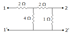
Answer: Option
Explanation:

22.
The internal impedance of a source is 3 + j 4 Ω. It is desired to supply maximum power to a resistive load. The load resistance should be
Answer: Option
Explanation:
RL = 32 + 42.
23.
In figure readings of the two voltmeters should be
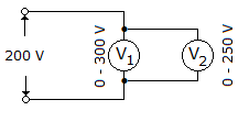
Answer: Option
Explanation:
Both voltmeter connected in parallel, hence read same voltage as applied.
24.
The internal impedance of a source is 3 + j 7 Ω. For maximum power transfer, load impedance should be
Answer: Option
Explanation:
Load impedance should be conjugate of source impedance.
25.
In the circuit of figure, the current through battery E3 is
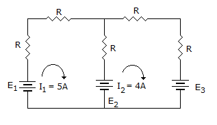
Answer: Option
Explanation:
4 A current is flowing into the battery. Therefore, it is charging current.
Quick links
Quantitative Aptitude
Verbal (English)
Reasoning
Programming
Interview
Placement Papers