Electronics and Communication Engineering - Networks Analysis and Synthesis
Exercise : Networks Analysis and Synthesis - Section 10
- Networks Analysis and Synthesis - Section 14
- Networks Analysis and Synthesis - Section 27
- Networks Analysis and Synthesis - Section 26
- Networks Analysis and Synthesis - Section 25
- Networks Analysis and Synthesis - Section 24
- Networks Analysis and Synthesis - Section 23
- Networks Analysis and Synthesis - Section 22
- Networks Analysis and Synthesis - Section 21
- Networks Analysis and Synthesis - Section 20
- Networks Analysis and Synthesis - Section 19
- Networks Analysis and Synthesis - Section 18
- Networks Analysis and Synthesis - Section 17
- Networks Analysis and Synthesis - Section 16
- Networks Analysis and Synthesis - Section 15
- Networks Analysis and Synthesis - Section 1
- Networks Analysis and Synthesis - Section 13
- Networks Analysis and Synthesis - Section 12
- Networks Analysis and Synthesis - Section 11
- Networks Analysis and Synthesis - Section 10
- Networks Analysis and Synthesis - Section 9
- Networks Analysis and Synthesis - Section 8
- Networks Analysis and Synthesis - Section 7
- Networks Analysis and Synthesis - Section 6
- Networks Analysis and Synthesis - Section 5
- Networks Analysis and Synthesis - Section 4
- Networks Analysis and Synthesis - Section 3
- Networks Analysis and Synthesis - Section 2
16.
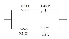
In figure the open circuit emf is
Answer: Option
Explanation:
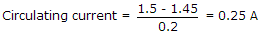
Since emfs of two cells are not equal, a circulating current flows.
 .
.
OC emf = 1.5 - (0.25)(0.1) = 1.475 V.
17.
In a practical current source, the load current
Answer: Option
Explanation:
In a current source the source resistance is in parallel with the source. Some current flows through this source resistance.
18.
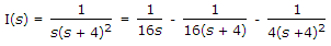
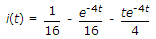
If 


Answer: Option
Explanation:
19.
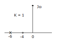
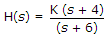
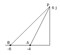
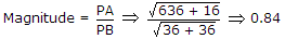
The pole zero diagram of an impedance Z has a pole at s = - 6 and zero at s = - 4 as shown in figure the constant multiplier k = 1. For a signal Is = cos 6t, the steady state voltage across Z is given in magnitude as under
Answer: Option
Explanation:
 .
.
20.
A resistor R of 1 Ω and two inductor L1 and L2 of inductances 1 H and 2 H respectively, are connected in parallel. At some time, the current through L1 and L2 are 1 A and 2 A, respectively. The current through R at time t = ∞ will be
Answer: Option
Explanation:
Resistor will get short circuited.
Quick links
Quantitative Aptitude
Verbal (English)
Reasoning
Programming
Interview
Placement Papers