Electronics and Communication Engineering - Networks Analysis and Synthesis
Exercise : Networks Analysis and Synthesis - Section 10
- Networks Analysis and Synthesis - Section 14
- Networks Analysis and Synthesis - Section 27
- Networks Analysis and Synthesis - Section 26
- Networks Analysis and Synthesis - Section 25
- Networks Analysis and Synthesis - Section 24
- Networks Analysis and Synthesis - Section 23
- Networks Analysis and Synthesis - Section 22
- Networks Analysis and Synthesis - Section 21
- Networks Analysis and Synthesis - Section 20
- Networks Analysis and Synthesis - Section 19
- Networks Analysis and Synthesis - Section 18
- Networks Analysis and Synthesis - Section 17
- Networks Analysis and Synthesis - Section 16
- Networks Analysis and Synthesis - Section 15
- Networks Analysis and Synthesis - Section 1
- Networks Analysis and Synthesis - Section 13
- Networks Analysis and Synthesis - Section 12
- Networks Analysis and Synthesis - Section 11
- Networks Analysis and Synthesis - Section 10
- Networks Analysis and Synthesis - Section 9
- Networks Analysis and Synthesis - Section 8
- Networks Analysis and Synthesis - Section 7
- Networks Analysis and Synthesis - Section 6
- Networks Analysis and Synthesis - Section 5
- Networks Analysis and Synthesis - Section 4
- Networks Analysis and Synthesis - Section 3
- Networks Analysis and Synthesis - Section 2
11.
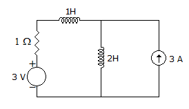
In figure, the steady state current through 1H inductance is
Answer: Option
Explanation:
In steady state inductance behaves as short-circuit.
12.
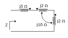
Impedance Z as shown in the given figure is
Answer: Option
Explanation:
Z = j5 + j2 + j2 + 20j - 20j = 9jΩ.
13.
A resistance R, inductance L and capacitance C are in series. The source frequency is adjusted to be equal to resonant frequency. The lower half power frequency is ω1. Another resistance R is added in series with the circuit. The new lower half power frequency will be
Answer: Option
Explanation:
As R increases, Q decreases, bandwidth =  . Therefore, bandwidth increases. Hence lower half power frequency will be less than ωr.
14.
The strength of controlled voltage source depends on
Answer: Option
Explanation:
A controlled voltage source may be a voltage source or current source and its strength may depend on another voltage or current.
15.
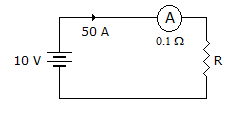
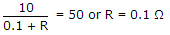
In figure, the value of R should be
Answer: Option
Explanation:
Quick links
Quantitative Aptitude
Verbal (English)
Reasoning
Programming
Interview
Placement Papers