Electronics and Communication Engineering - Networks Analysis and Synthesis
Exercise : Networks Analysis and Synthesis - Section 7
- Networks Analysis and Synthesis - Section 14
- Networks Analysis and Synthesis - Section 27
- Networks Analysis and Synthesis - Section 26
- Networks Analysis and Synthesis - Section 25
- Networks Analysis and Synthesis - Section 24
- Networks Analysis and Synthesis - Section 23
- Networks Analysis and Synthesis - Section 22
- Networks Analysis and Synthesis - Section 21
- Networks Analysis and Synthesis - Section 20
- Networks Analysis and Synthesis - Section 19
- Networks Analysis and Synthesis - Section 18
- Networks Analysis and Synthesis - Section 17
- Networks Analysis and Synthesis - Section 16
- Networks Analysis and Synthesis - Section 15
- Networks Analysis and Synthesis - Section 1
- Networks Analysis and Synthesis - Section 13
- Networks Analysis and Synthesis - Section 12
- Networks Analysis and Synthesis - Section 11
- Networks Analysis and Synthesis - Section 10
- Networks Analysis and Synthesis - Section 9
- Networks Analysis and Synthesis - Section 8
- Networks Analysis and Synthesis - Section 7
- Networks Analysis and Synthesis - Section 6
- Networks Analysis and Synthesis - Section 5
- Networks Analysis and Synthesis - Section 4
- Networks Analysis and Synthesis - Section 3
- Networks Analysis and Synthesis - Section 2
16.
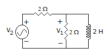
In figure, the voltage V1 = 4∠0 V. The source voltage V2 is
Answer: Option
Explanation:
IR = 2∠OA, I1 = 2∠-90° = -j 2A.
Total current = 2 - j2.
V2 = 2 (2 - j2) + 4∠0 = 8 - j4 volts.
17.
A capacitor whose capacitance Ct = C0 (1- cos ωt) is fed by a sinusoidal voltage v = V0 sin ωt. The equation for current i is
Answer: Option
Explanation:
i =  or i = C0 (1 - cos ωt) ωV0 cos ωt = C0ωV0 (cos ωt - cos2 ωt)
18.
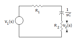
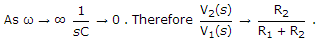
Figure shows an RC circuit. The magnitude plot V2/V1
Answer: Option
Explanation:
19.
Assertion (A): In a circuit having high inductance, reactive power may be more than apparent power.
Reason (R): Reactive power = VI sin θ.
Answer: Option
Explanation:
Reactive power cannot be more than apparent power.
20.
A two branch parallel circuit has a 10 Ω resistance and 0.5 H inductance in one branch and a 100 μF capacitor in the second branch. It is fed from 100 V ac supply. At resonance, the source current is
Answer: Option
Explanation:
At parallel resonance source current = 
Quick links
Quantitative Aptitude
Verbal (English)
Reasoning
Programming
Interview
Placement Papers