Electronics and Communication Engineering - Networks Analysis and Synthesis
Exercise : Networks Analysis and Synthesis - Section 6
- Networks Analysis and Synthesis - Section 14
- Networks Analysis and Synthesis - Section 27
- Networks Analysis and Synthesis - Section 26
- Networks Analysis and Synthesis - Section 25
- Networks Analysis and Synthesis - Section 24
- Networks Analysis and Synthesis - Section 23
- Networks Analysis and Synthesis - Section 22
- Networks Analysis and Synthesis - Section 21
- Networks Analysis and Synthesis - Section 20
- Networks Analysis and Synthesis - Section 19
- Networks Analysis and Synthesis - Section 18
- Networks Analysis and Synthesis - Section 17
- Networks Analysis and Synthesis - Section 16
- Networks Analysis and Synthesis - Section 15
- Networks Analysis and Synthesis - Section 1
- Networks Analysis and Synthesis - Section 13
- Networks Analysis and Synthesis - Section 12
- Networks Analysis and Synthesis - Section 11
- Networks Analysis and Synthesis - Section 10
- Networks Analysis and Synthesis - Section 9
- Networks Analysis and Synthesis - Section 8
- Networks Analysis and Synthesis - Section 7
- Networks Analysis and Synthesis - Section 6
- Networks Analysis and Synthesis - Section 5
- Networks Analysis and Synthesis - Section 4
- Networks Analysis and Synthesis - Section 3
- Networks Analysis and Synthesis - Section 2
31.
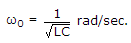
A parallel RLC network has R = 4Ω, L = 4H, C = 0.25F. Then at resonance Q =
Answer: Option
Explanation:
 For parallel resonant circuit
32.
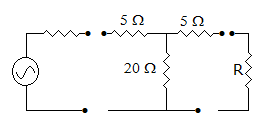
A T network is inserted between source and R as shown in figure. The resistance seen by the source remains the same with or without T network when R is
Answer: Option
Explanation:
If R = 15 Ω resistance, seen by the source = 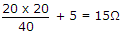 .
.
33.
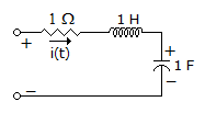
The circuit shown in the figure has initial current iL(0) = 1A through the inductor and an initial voltage vc(0) = 1 V across the capacitor. For input v(t) = U(t) the Laplace transform of the current i(t) for t ≥ 0 is


Answer: Option
Explanation:
Apply KVL
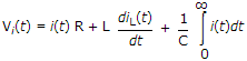
 Vi(s) = I(s).R + Ls I(s) - Li(0+) +
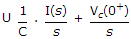
Put the given values and 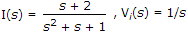 .
.
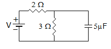
34.
In figure, the time constant for the capacitor charging is
Answer: Option
Explanation:
Effective resistence is  . Hence RC = 6 μs.
35.
In figure, the short circuit current through terminal AB will be
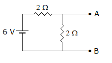
Answer: Option
Explanation:
No current will flow through 2Ω resistance in parallel with short-circuit.
Quick links
Quantitative Aptitude
Verbal (English)
Reasoning
Programming
Interview
Placement Papers