Electronics and Communication Engineering - Networks Analysis and Synthesis
Exercise : Networks Analysis and Synthesis - Section 5
- Networks Analysis and Synthesis - Section 14
- Networks Analysis and Synthesis - Section 27
- Networks Analysis and Synthesis - Section 26
- Networks Analysis and Synthesis - Section 25
- Networks Analysis and Synthesis - Section 24
- Networks Analysis and Synthesis - Section 23
- Networks Analysis and Synthesis - Section 22
- Networks Analysis and Synthesis - Section 21
- Networks Analysis and Synthesis - Section 20
- Networks Analysis and Synthesis - Section 19
- Networks Analysis and Synthesis - Section 18
- Networks Analysis and Synthesis - Section 17
- Networks Analysis and Synthesis - Section 16
- Networks Analysis and Synthesis - Section 15
- Networks Analysis and Synthesis - Section 1
- Networks Analysis and Synthesis - Section 13
- Networks Analysis and Synthesis - Section 12
- Networks Analysis and Synthesis - Section 11
- Networks Analysis and Synthesis - Section 10
- Networks Analysis and Synthesis - Section 9
- Networks Analysis and Synthesis - Section 8
- Networks Analysis and Synthesis - Section 7
- Networks Analysis and Synthesis - Section 6
- Networks Analysis and Synthesis - Section 5
- Networks Analysis and Synthesis - Section 4
- Networks Analysis and Synthesis - Section 3
- Networks Analysis and Synthesis - Section 2
21.
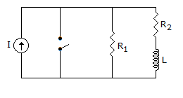
The switch in figure is initially closed. At t = 0 the switch is opened. At t = 0+, the current through inductance is

I
0

Answer: Option
Explanation:
At t = ∞ inductance behaves as open circuit.
22.
A constant k low pass T section filter has a characteristic impedance of 600 p at zero frequency. At f = fc the characteristic impedance is
Answer: Option
Explanation:
Z0T = R0(1 - f2 / fc2)0.5. At f = f0. Z0T = 0.
23.
The resonant frequency of the circuit shown in figure is
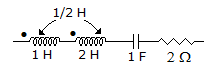

4p Hz
2 p Hz
at all frequency
Answer: Option
Explanation:
Leq = L1 + L2 + 2m = 1 + 2 + 2 x  = 4
= 4
 .
.
24.
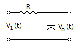
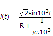
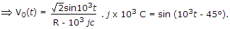
For the circuit shown in the figure, the time constant RC = 1 ms. The input voltage is V1(t) = 2 sin 103 t. The output voltage V0(t) is equal to
Answer: Option
Explanation:
V0(t) = i(t) . jωc 

25.
Bus bars are always meant for very heavy currents.
Answer: Option
Explanation:
Bus bars are used for heavy as well as light currents.
Quick links
Quantitative Aptitude
Verbal (English)
Reasoning
Programming
Interview
Placement Papers