Electronics and Communication Engineering - Networks Analysis and Synthesis
Exercise : Networks Analysis and Synthesis - Section 2
- Networks Analysis and Synthesis - Section 14
- Networks Analysis and Synthesis - Section 27
- Networks Analysis and Synthesis - Section 26
- Networks Analysis and Synthesis - Section 25
- Networks Analysis and Synthesis - Section 24
- Networks Analysis and Synthesis - Section 23
- Networks Analysis and Synthesis - Section 22
- Networks Analysis and Synthesis - Section 21
- Networks Analysis and Synthesis - Section 20
- Networks Analysis and Synthesis - Section 19
- Networks Analysis and Synthesis - Section 18
- Networks Analysis and Synthesis - Section 17
- Networks Analysis and Synthesis - Section 16
- Networks Analysis and Synthesis - Section 15
- Networks Analysis and Synthesis - Section 1
- Networks Analysis and Synthesis - Section 13
- Networks Analysis and Synthesis - Section 12
- Networks Analysis and Synthesis - Section 11
- Networks Analysis and Synthesis - Section 10
- Networks Analysis and Synthesis - Section 9
- Networks Analysis and Synthesis - Section 8
- Networks Analysis and Synthesis - Section 7
- Networks Analysis and Synthesis - Section 6
- Networks Analysis and Synthesis - Section 5
- Networks Analysis and Synthesis - Section 4
- Networks Analysis and Synthesis - Section 3
- Networks Analysis and Synthesis - Section 2
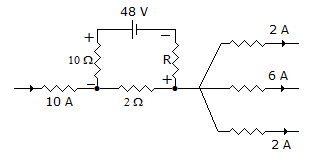
11.
In figure the voltage drop across the 10 Ω resistance is 10 V. The resistance R
Answer: Option
Explanation:
Current supplied by battery =  Therefore current through 2Ω resistance is 11 A. Voltage across R = 48 - 10 - 11 x 2 = 16 V.
12.
A two branch parallel tuned circuit has a coil of resistance 100 Ω and inductance 0.005 H in one branch and 10 nF capacitor in the second branch. At resonance frequency is
Answer: Option
Explanation:
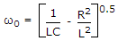 =
= 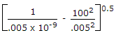 = 44.67 x 10⁴ rad/sec.
13.
A circuit is replaced by its Thevenin's equivalent to find current through a certain branch. If VTH = 10 V and RTH = 20 Ω, the current through the branch
Answer: Option
Explanation:
 Hence less than 0.5 A.
14.
An ideal transformer has a turn ratio of 2 : 1. Taking hv side as port 1 and lv side as port 2, transmission parameters of transformer are


Answer: Option
Explanation:
For the given data V1 = 2V2 and I1 = 0.5 I2 .
15.
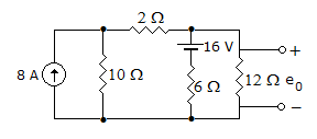
The voltage e0 in the figure
Answer: Option
Explanation:
Apply mesh analysis in both the mesh by converting 8A current source into voltage source.
80 = 18 I1 - 6I2 + 16
1 - 12I2 - 6I2 + 6I1 = - 16
 I1 = 4.3A, I2 = 2.3A
Hence e0 = 13I2 13 x 2.3 28 volts.
Quick links
Quantitative Aptitude
Verbal (English)
Reasoning
Programming
Interview
Placement Papers