Electronics and Communication Engineering - Networks Analysis and Synthesis
Exercise : Networks Analysis and Synthesis - Section 2
- Networks Analysis and Synthesis - Section 14
- Networks Analysis and Synthesis - Section 27
- Networks Analysis and Synthesis - Section 26
- Networks Analysis and Synthesis - Section 25
- Networks Analysis and Synthesis - Section 24
- Networks Analysis and Synthesis - Section 23
- Networks Analysis and Synthesis - Section 22
- Networks Analysis and Synthesis - Section 21
- Networks Analysis and Synthesis - Section 20
- Networks Analysis and Synthesis - Section 19
- Networks Analysis and Synthesis - Section 18
- Networks Analysis and Synthesis - Section 17
- Networks Analysis and Synthesis - Section 16
- Networks Analysis and Synthesis - Section 15
- Networks Analysis and Synthesis - Section 1
- Networks Analysis and Synthesis - Section 13
- Networks Analysis and Synthesis - Section 12
- Networks Analysis and Synthesis - Section 11
- Networks Analysis and Synthesis - Section 10
- Networks Analysis and Synthesis - Section 9
- Networks Analysis and Synthesis - Section 8
- Networks Analysis and Synthesis - Section 7
- Networks Analysis and Synthesis - Section 6
- Networks Analysis and Synthesis - Section 5
- Networks Analysis and Synthesis - Section 4
- Networks Analysis and Synthesis - Section 3
- Networks Analysis and Synthesis - Section 2
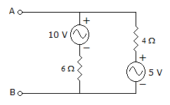
6.
In the given circuit, viewed from AB, the circuit can be reduced to an equivalent circuit as
Answer: Option
Explanation:
For RTh, Voltage source will be short circuited RTh = 2.4 Ω, 
VAB = 10 - 6 I  7 V.
7 V.
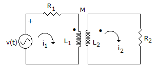
7.
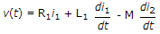
For the network of figure KVL for first loop is
Answer: Option
Explanation:
M term is negative because i1, is entering the dotted terminal and i2, is leaving the dotted terminal.
8.
An RC series circuit is charged by a voltage E. After a long time the battery is removed and a short circuit is placed across R-C. Then
Answer: Option
Explanation:
Direction of current during discharging is opposite to that during charging.
9.
Two coils having self inductances of 10 mH and 40 mH are mutually coupled. The maximum possible mutual inductance is
Answer: Option
Explanation:
Maximum mutual inductance = L1L2 = 20 mH.
10.
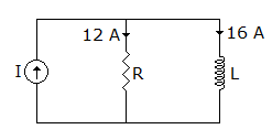
In the circuit shown in figure the current I of sinusoidal source is
Answer: Option
Explanation:
Currents in resistance and inductance are out of phase by 90°. Hence I = 122 + 162 = 20 A.
Quick links
Quantitative Aptitude
Verbal (English)
Reasoning
Programming
Interview
Placement Papers