Electronics and Communication Engineering - Networks Analysis and Synthesis
Exercise : Networks Analysis and Synthesis - Section 1
- Networks Analysis and Synthesis - Section 14
- Networks Analysis and Synthesis - Section 27
- Networks Analysis and Synthesis - Section 26
- Networks Analysis and Synthesis - Section 25
- Networks Analysis and Synthesis - Section 24
- Networks Analysis and Synthesis - Section 23
- Networks Analysis and Synthesis - Section 22
- Networks Analysis and Synthesis - Section 21
- Networks Analysis and Synthesis - Section 20
- Networks Analysis and Synthesis - Section 19
- Networks Analysis and Synthesis - Section 18
- Networks Analysis and Synthesis - Section 17
- Networks Analysis and Synthesis - Section 16
- Networks Analysis and Synthesis - Section 15
- Networks Analysis and Synthesis - Section 1
- Networks Analysis and Synthesis - Section 13
- Networks Analysis and Synthesis - Section 12
- Networks Analysis and Synthesis - Section 11
- Networks Analysis and Synthesis - Section 10
- Networks Analysis and Synthesis - Section 9
- Networks Analysis and Synthesis - Section 8
- Networks Analysis and Synthesis - Section 7
- Networks Analysis and Synthesis - Section 6
- Networks Analysis and Synthesis - Section 5
- Networks Analysis and Synthesis - Section 4
- Networks Analysis and Synthesis - Section 3
- Networks Analysis and Synthesis - Section 2
16.
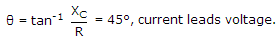
A series RC circuit has R = 5 Ω and C = 10 μF. The current in the circuit is 5 sin 20000t. The applied voltage is
Answer: Option
Explanation:
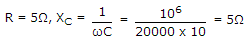
Z = R2 + XC2 = 50
V = 550 sin(20000 t - 45°)
V = 252 sin(20000 t - 45°)
17.
A capacitor stores 0.15C at 5 V. Its capacitance is
Answer: Option
Explanation:
Q = CV or 0.15 = C(5) or C = 0.03 F.
18.
A 0.5 μF capacitor is connected across a 10 V battery. After a long time, the circuit current and voltage across capacitor will be
Answer: Option
Explanation:
When the capacitor is fully charged, i = 0 and voltage across capacitor is equal to battery voltage.
19.
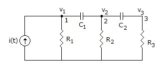
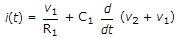
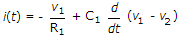
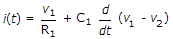
For node 1 in figure, KCL equation is
none of the above
Answer: Option
Explanation:
i(t) is the incoming current. The currents leaving node 1 are 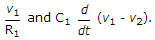
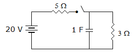
20.
In the circuit of figure, the switch is closed at t = 0. At t = 0+ the current through C is
Answer: Option
Explanation:
Capacitor behaves as a short-circuit at t = 0.
Quick links
Quantitative Aptitude
Verbal (English)
Reasoning
Programming
Interview
Placement Papers