Digital Electronics - Counters

Exercise : Counters - General Questions
41.
In an HDL ring counter, many invalid states are included in the programming by:
using a case statement.
using an elsif statement.
including them under others.
the ser_in line.
Answer: Option
Explanation:
No answer description is available. Let's discuss.

42.
In a VHDL retriggerable edge-triggered one-shot, which condition will not exist when a clock edge occurs?
A trigger edge has occurred and we must load the counter.
The counter is zero and we need to keep it at zero.
The shift register is reset.
The counter is not zero and we need to count down by one.
Answer: Option
Explanation:
No answer description is available. Let's discuss.

43.

What function does the CTR DIV 8 circuit given below perform?
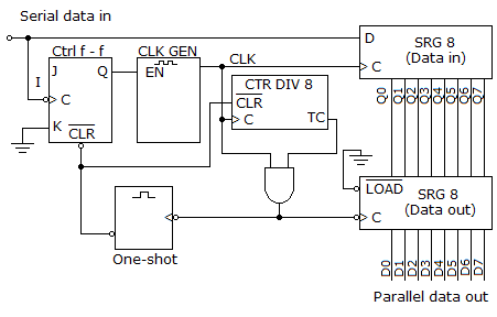
It divides the clock frequency down to match the frequency of the serial data in.
The divide-by-8 counter is triggered by the control flip-flop and clock, which then allows the data output register to begin storing the input data. Once all eight data bits are stored in the data output register, the data output register and the divide-by-8 counter trigger the one-shot. The one-shot then begins the process all over again.
The divide-by-8 counter is used to verify that the parity bit is attached to the input data string.
It keeps track of the eight data bits, triggering the transfer of the data through the output register and the one-shot, which then resets the control flip-flop and divide-by-8 counter.
Answer: Option
Explanation:
No answer description is available. Let's discuss.

44.
Synchronous (parallel) counters eliminate the delay problems encountered with asynchronous (ripple) counters because the:
input clock pulses are applied only to the first and last stages.
input clock pulses are applied only to the last stage.
input clock pulses are applied simultaneously to each stage.
input clock pulses are not used to activate any of the counter stages.
Answer: Option
Explanation:
No answer description is available. Let's discuss.

45.
List the state of each output pin of a 7447 if RBI = 0, LT = 1, A0 = 1, A1 = 0, A2 = 0, and A3 = 1.
RBO = 0, a = 0, b = 0, c = 0, d = 1, e = 1, f = 0, g = 0
RBO = 1, a = 0, b = 0, c = 0, d = 1, e = 1, f = 0, g = 0
RBO = 0, a = 0, b = 0, c = 0, d = 0, e = 1, f = 0, g = 0
RBO = 1, a = 0, b = 0, c = 0, d = 0, e = 1, f = 0, g = 0
Answer: Option
Explanation:
No answer description is available. Let's discuss.