Digital Electronics - Counters
Exercise : Counters - General Questions
- Counters - General Questions
- Counters - True or False
- Counters - Filling the Blanks
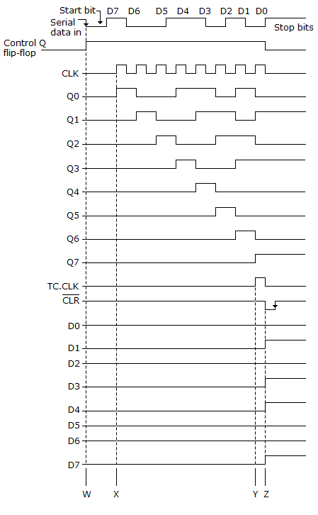
46.
Referring to the given figure, what causes the Control FF to reset after D7?
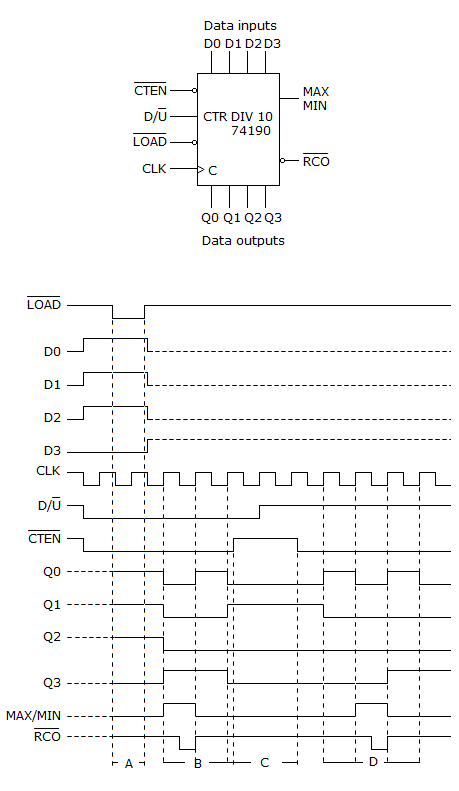
47.
What function will the counter shown below be performing during period "B" on the timing diagram?
48.
Three cascaded decade counters will divide the input frequency by ________.
49.
A counter with a modulus of 16 acts as a ________.
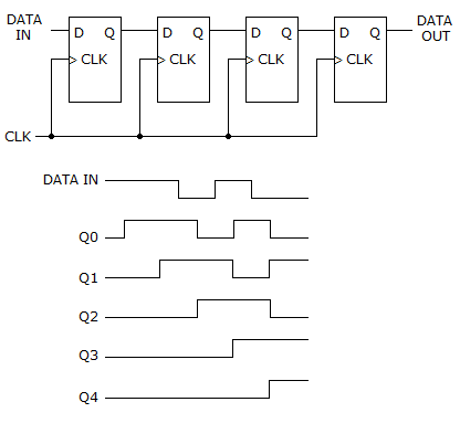
50.
How many data bits can be stored in the register shown below?
Quick links
Quantitative Aptitude
Verbal (English)
Reasoning
Programming
Interview
Placement Papers