Electronics and Communication Engineering - Networks Analysis and Synthesis
Exercise : Networks Analysis and Synthesis - Section 21
- Networks Analysis and Synthesis - Section 14
- Networks Analysis and Synthesis - Section 27
- Networks Analysis and Synthesis - Section 26
- Networks Analysis and Synthesis - Section 25
- Networks Analysis and Synthesis - Section 24
- Networks Analysis and Synthesis - Section 23
- Networks Analysis and Synthesis - Section 22
- Networks Analysis and Synthesis - Section 21
- Networks Analysis and Synthesis - Section 20
- Networks Analysis and Synthesis - Section 19
- Networks Analysis and Synthesis - Section 18
- Networks Analysis and Synthesis - Section 17
- Networks Analysis and Synthesis - Section 16
- Networks Analysis and Synthesis - Section 15
- Networks Analysis and Synthesis - Section 1
- Networks Analysis and Synthesis - Section 13
- Networks Analysis and Synthesis - Section 12
- Networks Analysis and Synthesis - Section 11
- Networks Analysis and Synthesis - Section 10
- Networks Analysis and Synthesis - Section 9
- Networks Analysis and Synthesis - Section 8
- Networks Analysis and Synthesis - Section 7
- Networks Analysis and Synthesis - Section 6
- Networks Analysis and Synthesis - Section 5
- Networks Analysis and Synthesis - Section 4
- Networks Analysis and Synthesis - Section 3
- Networks Analysis and Synthesis - Section 2
6.
A two terminal black box contains one of the elements R, L, C. The black box is connected to 220 V as supply. The current is I, when a capacitance of 0.1 F is connected in series between the source and box, the current is 2I. The elements is
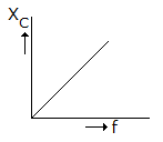
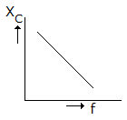
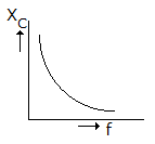
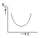
7.
Which of the following graphs in figure correctly represents the variation of capacitive reactance with frequency?
8.
If Z(s) is positive real, then 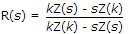 where k has only positive real values is also positive real. This hypothesis was first given by
where k has only positive real values is also positive real. This hypothesis was first given by9.
For a voltage transfer function H(s), realizable by RLC network, the following statements are made
- H(s) cannot have a pole at s = 0
- H(s) cannot have a pole at s = ± j4
- H(s) cannot have a pole at s = ∞
- H(s) cannot have a pole at s = + 2
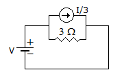
10.
In figure the effective resistance faced by voltage source is
Quick links
Quantitative Aptitude
Verbal (English)
Reasoning
Programming
Interview
Placement Papers