Electronics and Communication Engineering - Networks Analysis and Synthesis
Exercise : Networks Analysis and Synthesis - Section 13
- Networks Analysis and Synthesis - Section 14
- Networks Analysis and Synthesis - Section 27
- Networks Analysis and Synthesis - Section 26
- Networks Analysis and Synthesis - Section 25
- Networks Analysis and Synthesis - Section 24
- Networks Analysis and Synthesis - Section 23
- Networks Analysis and Synthesis - Section 22
- Networks Analysis and Synthesis - Section 21
- Networks Analysis and Synthesis - Section 20
- Networks Analysis and Synthesis - Section 19
- Networks Analysis and Synthesis - Section 18
- Networks Analysis and Synthesis - Section 17
- Networks Analysis and Synthesis - Section 16
- Networks Analysis and Synthesis - Section 15
- Networks Analysis and Synthesis - Section 1
- Networks Analysis and Synthesis - Section 13
- Networks Analysis and Synthesis - Section 12
- Networks Analysis and Synthesis - Section 11
- Networks Analysis and Synthesis - Section 10
- Networks Analysis and Synthesis - Section 9
- Networks Analysis and Synthesis - Section 8
- Networks Analysis and Synthesis - Section 7
- Networks Analysis and Synthesis - Section 6
- Networks Analysis and Synthesis - Section 5
- Networks Analysis and Synthesis - Section 4
- Networks Analysis and Synthesis - Section 3
- Networks Analysis and Synthesis - Section 2
46.
The electrolyte in a dry cell is completely dry.
Answer: Option
Explanation:
The electrolyte is moist.
47.
A series RLC circuit has a resonant frequency of 2000 Hz. The maximum voltage across C is likely to occur at a frequency of about
Answer: Option
Explanation:
The maximum voltage across inductance occurs at a frequency slightly above the resonant frequency.
48.
Assertion (A): Thevenin's theorem and Norton's theorem are dual of each other.
Reason (R): Voltage source can be converted into current source and vice versa.
Answer: Option
Explanation:
Thevenin's circuit uses a voltage source and Norton's circuit uses a current source.
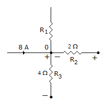
49.
In the network shown in figure, the voltage drops across R2 and R3 are 10 V and 16 V with polarities as shown. The current in R1
Answer: Option
Explanation:
Current through R2 = 5 A towards 0. Current through R3 is 4 A away from node. Total incoming current = 13 A. Current going away from 0 and flowing through R1 = 9 A.
50.
A coil has a resistance of 2 Ω and inductance of 0.1 mH. The applied voltages is suddenly increased from 10 V to 20 V. After steady state condition have reached, the current is
Answer: Option
Explanation:
The final steady state current in RL circuit depends only on final voltage (i.e., 20 V) and resistance.
Quick links
Quantitative Aptitude
Verbal (English)
Reasoning
Programming
Interview
Placement Papers