Electronics and Communication Engineering - Networks Analysis and Synthesis
Exercise : Networks Analysis and Synthesis - Section 7
- Networks Analysis and Synthesis - Section 14
- Networks Analysis and Synthesis - Section 27
- Networks Analysis and Synthesis - Section 26
- Networks Analysis and Synthesis - Section 25
- Networks Analysis and Synthesis - Section 24
- Networks Analysis and Synthesis - Section 23
- Networks Analysis and Synthesis - Section 22
- Networks Analysis and Synthesis - Section 21
- Networks Analysis and Synthesis - Section 20
- Networks Analysis and Synthesis - Section 19
- Networks Analysis and Synthesis - Section 18
- Networks Analysis and Synthesis - Section 17
- Networks Analysis and Synthesis - Section 16
- Networks Analysis and Synthesis - Section 15
- Networks Analysis and Synthesis - Section 1
- Networks Analysis and Synthesis - Section 13
- Networks Analysis and Synthesis - Section 12
- Networks Analysis and Synthesis - Section 11
- Networks Analysis and Synthesis - Section 10
- Networks Analysis and Synthesis - Section 9
- Networks Analysis and Synthesis - Section 8
- Networks Analysis and Synthesis - Section 7
- Networks Analysis and Synthesis - Section 6
- Networks Analysis and Synthesis - Section 5
- Networks Analysis and Synthesis - Section 4
- Networks Analysis and Synthesis - Section 3
- Networks Analysis and Synthesis - Section 2
36.
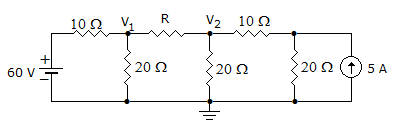
In the figure circuit, V1 = 40 V. When R is 10 Ω. When R is zero, the value of V2 will be
Answer: Option
Explanation:
When R = 0, it will be short circuited and 10 Ω and 20 Ω will come in series, and potential across V1 will become 40 V by divider rule.
37.
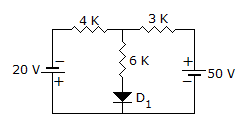
The Thevenin Resistance of the circuit is
Answer: Option
Explanation:
Diode is a non linear circuit it will be removed
Nodal analysis
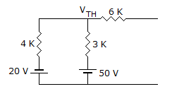
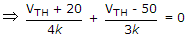
VTH = 20volt.
38.
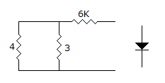
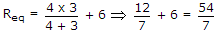
In the circuit shown in the given figure, RL will absorb maximum power when its value is
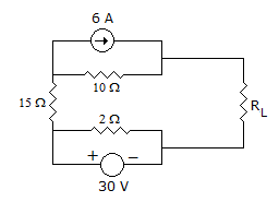
Answer: Option
Explanation:
Circuit can be rearranged as follows
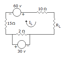
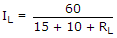

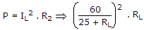
Now find  and find RL = ?.
39.
In an RC series circuit excited by dc voltage E, the current at t = 0 is
Answer: Option
Explanation:
Since the capacitor does not have any charge initially, 
40.
The current through a 10 Ω resistance in a dc circuit having two emf sources is 3A. If this resistance is changed to 20 Ω, the new value of current will be
Answer: Option
Explanation:
The current will be less than 3 A. It may not be 1.5 A because other resistance in the circuit also affect the value of current.
Quick links
Quantitative Aptitude
Verbal (English)
Reasoning
Programming
Interview
Placement Papers