Electronics and Communication Engineering - Networks Analysis and Synthesis
Exercise : Networks Analysis and Synthesis - Section 5
- Networks Analysis and Synthesis - Section 14
- Networks Analysis and Synthesis - Section 27
- Networks Analysis and Synthesis - Section 26
- Networks Analysis and Synthesis - Section 25
- Networks Analysis and Synthesis - Section 24
- Networks Analysis and Synthesis - Section 23
- Networks Analysis and Synthesis - Section 22
- Networks Analysis and Synthesis - Section 21
- Networks Analysis and Synthesis - Section 20
- Networks Analysis and Synthesis - Section 19
- Networks Analysis and Synthesis - Section 18
- Networks Analysis and Synthesis - Section 17
- Networks Analysis and Synthesis - Section 16
- Networks Analysis and Synthesis - Section 15
- Networks Analysis and Synthesis - Section 1
- Networks Analysis and Synthesis - Section 13
- Networks Analysis and Synthesis - Section 12
- Networks Analysis and Synthesis - Section 11
- Networks Analysis and Synthesis - Section 10
- Networks Analysis and Synthesis - Section 9
- Networks Analysis and Synthesis - Section 8
- Networks Analysis and Synthesis - Section 7
- Networks Analysis and Synthesis - Section 6
- Networks Analysis and Synthesis - Section 5
- Networks Analysis and Synthesis - Section 4
- Networks Analysis and Synthesis - Section 3
- Networks Analysis and Synthesis - Section 2
6.
A series R-L circuit has R = 1 Ω and L = 1 H. It is excited by a V battery at t = 0. The steady state condition is reached at
Answer: Option
Explanation:
i = 10 (1 - e-t). It reaches steadily state value at t = ∞
7.
The current source in figure, can be replaced by
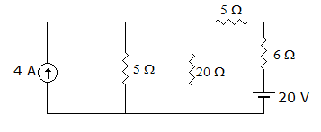
Answer: Option
Explanation:
The parallel combination of 20 Ω and 5 Ω is 4 Ω. Therefore, strength of current source is 4 x 4 = 16 A and source resistance is 4 ohms.
8.
If the voltage across the last resistor is V, and all the resistor is unity. Then Vs is given by
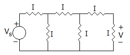
Answer: Option
Explanation:
Let the last voltage is V1 = V, V2 = Voltage across both 1 Ω resistor
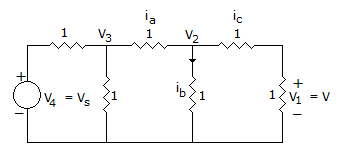
 V + V = 2V
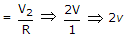
Current in shunt resistor = i
ia = ib + ic
2v + v 3v
V3 = ib x R + ia x R
3v + 2v = 5v
V4 = 5v + 8v = 13v.
9.
In figure, iL at t = 0+ is
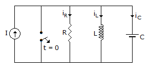
0
I
infinite

Answer: Option
Explanation:
Inductance behaves as O.C. at t = 0+.
10.
In a purely inductive circuit, the current __________ the voltage by __________ .
Answer: Option
Explanation:
In inductive circuit current lags the voltage by 90°.
Quick links
Quantitative Aptitude
Verbal (English)
Reasoning
Programming
Interview
Placement Papers