Electronics and Communication Engineering - Exam Questions Papers - Discussion
Discussion Forum : Exam Questions Papers - Exam Paper 12 (Q.No. 26)
26.
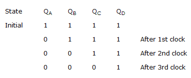
Figure shows four D type FFs are connected as a shift register using an XOR gate. The initial state and 3 subsequent states for 3 clock pulses are also given
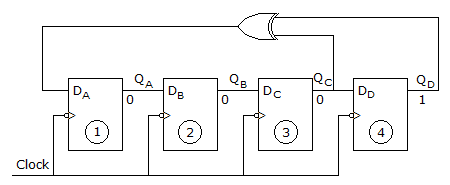
The state QA QB QC QD after the 4th clock pulse is
The state QA QB QC QD after the 4th clock pulse is
Answer: Option
Explanation:
After the 3rd pulse FF3 is 0 and FF4 is 1, so that XOR output is 1 which is fed to DA.
So, QA = 1, QA to QB → 0
AB to AC → 0, QC → QD → 0.
Discussion:
Be the first person to comment on this question !
Post your comments here:
Quick links
Quantitative Aptitude
Verbal (English)
Reasoning
Programming
Interview
Placement Papers