Electronics and Communication Engineering - Electronic Devices and Circuits
Exercise : Electronic Devices and Circuits - Section 4
- Electronic Devices and Circuits - Section 13
- Electronic Devices and Circuits - Section 24
- Electronic Devices and Circuits - Section 23
- Electronic Devices and Circuits - Section 22
- Electronic Devices and Circuits - Section 21
- Electronic Devices and Circuits - Section 20
- Electronic Devices and Circuits - Section 19
- Electronic Devices and Circuits - Section 18
- Electronic Devices and Circuits - Section 17
- Electronic Devices and Circuits - Section 16
- Electronic Devices and Circuits - Section 15
- Electronic Devices and Circuits - Section 14
- Electronic Devices and Circuits - Section 1
- Electronic Devices and Circuits - Section 12
- Electronic Devices and Circuits - Section 11
- Electronic Devices and Circuits - Section 10
- Electronic Devices and Circuits - Section 9
- Electronic Devices and Circuits - Section 8
- Electronic Devices and Circuits - Section 7
- Electronic Devices and Circuits - Section 6
- Electronic Devices and Circuits - Section 5
- Electronic Devices and Circuits - Section 4
- Electronic Devices and Circuits - Section 3
- Electronic Devices and Circuits - Section 2
21.
The modulus of counter in the given figure is
Answer: Option
Explanation:
Third clock pulse resets the counter to 00 state. Hence mod is 3.
22.
The input to a parity detector is 1001. The output is
Answer: Option
Explanation:
Since the number of 1 's is even, output is 0.
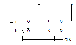
23.
A 4 bit modulo 16 ripple counter uses JK flip-flops. If the propagation delay of each FF is 50 ns. The max. clock frequency that can be used is equal to
Answer: Option
Explanation:
Propagation Delay for one FF is 50 nsec. For 4 FF = 50 x 4 = 200 nsec.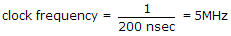 .
.
24.
As the number of flip flops are increased, the total propagation delay of
Answer: Option
Explanation:
In ripple counter the clock pulses are applied to one flip- flop only.
Hence as the number of flip-flops increases the delay increases.
In synchronous counter clock pulses to all flip-flops are applied simultaneously.
25.
In a 4 input OR gate, the total number of High outputs for the 16 input states are
Answer: Option
Explanation:
OR gate gives high output when one or more inputs are high.
Quick links
Quantitative Aptitude
Verbal (English)
Reasoning
Programming
Interview
Placement Papers