Electronics and Communication Engineering - Electronic Devices and Circuits
Exercise : Electronic Devices and Circuits - Section 20
- Electronic Devices and Circuits - Section 14
- Electronic Devices and Circuits - Section 27
- Electronic Devices and Circuits - Section 26
- Electronic Devices and Circuits - Section 25
- Electronic Devices and Circuits - Section 24
- Electronic Devices and Circuits - Section 23
- Electronic Devices and Circuits - Section 22
- Electronic Devices and Circuits - Section 21
- Electronic Devices and Circuits - Section 20
- Electronic Devices and Circuits - Section 19
- Electronic Devices and Circuits - Section 18
- Electronic Devices and Circuits - Section 17
- Electronic Devices and Circuits - Section 16
- Electronic Devices and Circuits - Section 15
- Electronic Devices and Circuits - Section 1
- Electronic Devices and Circuits - Section 13
- Electronic Devices and Circuits - Section 12
- Electronic Devices and Circuits - Section 11
- Electronic Devices and Circuits - Section 10
- Electronic Devices and Circuits - Section 9
- Electronic Devices and Circuits - Section 8
- Electronic Devices and Circuits - Section 7
- Electronic Devices and Circuits - Section 6
- Electronic Devices and Circuits - Section 5
- Electronic Devices and Circuits - Section 4
- Electronic Devices and Circuits - Section 3
- Electronic Devices and Circuits - Section 2
16.
The opposition of an inductor to current flow
17.
In a highly capacitive circuit the
18.
In ac circuits maximum power is delivered to a load if load impedance is conjugate of source impedance.
19.
In a series R-L-C circuit at the resonant frequency the
20.
The transfer function H(s) of a system is given by 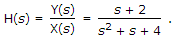 Given that understeady state conditions, the sinusoidal I/P and 0/P are respectively x(t) = cos 2t and y(t) = cos (2t + Φ), then the angle Φ will be
Given that understeady state conditions, the sinusoidal I/P and 0/P are respectively x(t) = cos 2t and y(t) = cos (2t + Φ), then the angle Φ will beQuick links
Quantitative Aptitude
Verbal (English)
Reasoning
Programming
Interview
Placement Papers