Electronics and Communication Engineering - Electronic Devices and Circuits
Exercise : Electronic Devices and Circuits - Section 10
- Electronic Devices and Circuits - Section 14
- Electronic Devices and Circuits - Section 27
- Electronic Devices and Circuits - Section 26
- Electronic Devices and Circuits - Section 25
- Electronic Devices and Circuits - Section 24
- Electronic Devices and Circuits - Section 23
- Electronic Devices and Circuits - Section 22
- Electronic Devices and Circuits - Section 21
- Electronic Devices and Circuits - Section 20
- Electronic Devices and Circuits - Section 19
- Electronic Devices and Circuits - Section 18
- Electronic Devices and Circuits - Section 17
- Electronic Devices and Circuits - Section 16
- Electronic Devices and Circuits - Section 15
- Electronic Devices and Circuits - Section 1
- Electronic Devices and Circuits - Section 13
- Electronic Devices and Circuits - Section 12
- Electronic Devices and Circuits - Section 11
- Electronic Devices and Circuits - Section 10
- Electronic Devices and Circuits - Section 9
- Electronic Devices and Circuits - Section 8
- Electronic Devices and Circuits - Section 7
- Electronic Devices and Circuits - Section 6
- Electronic Devices and Circuits - Section 5
- Electronic Devices and Circuits - Section 4
- Electronic Devices and Circuits - Section 3
- Electronic Devices and Circuits - Section 2
1.
Two phasors having rms values V1 and V2 which are added to give a phasor having rms value V3. V3 is maximum if phase angle between V1 and V2 is
Answer: Option
Explanation:
Sum of phasors is maximum if they are in phase and 360° = 0.
2.
A current of 1 A in the coil of an iron cored electromagnet cause a flux density of 0.2.T. If the current is 2 A, B=
Answer: Option
Explanation:
In air cored coil flux density increases linearly with current because there is no saturation.
3.
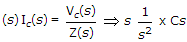
If the L.T. of the voltage across a capacitor of value 1/3 F is 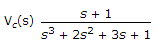 , then the value of the current through the capacitor at t = 0+ is
, then the value of the current through the capacitor at t = 0+ isAnswer: Option
Explanation:
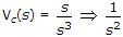
t → 0+  s → ∞ and s3 >> s2 >> s >> 1
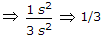 .
.
4.
In figure, the current I4 is
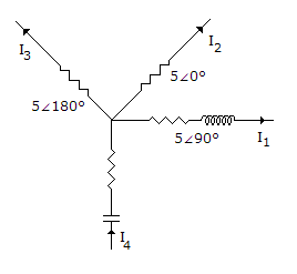
Answer: Option
Explanation:
I4 = I1 + I2 + I3
or I4 = 5∠90° + 5∠0 + 5∠180° = 5∠90°.
5.
For the circuit shown in the figure, the current I is
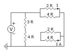
Answer: Option
Explanation:
V must be given.
Quick links
Quantitative Aptitude
Verbal (English)
Reasoning
Programming
Interview
Placement Papers