Electronics and Communication Engineering - Electronic Devices and Circuits
Exercise : Electronic Devices and Circuits - Section 5
- Electronic Devices and Circuits - Section 14
- Electronic Devices and Circuits - Section 27
- Electronic Devices and Circuits - Section 26
- Electronic Devices and Circuits - Section 25
- Electronic Devices and Circuits - Section 24
- Electronic Devices and Circuits - Section 23
- Electronic Devices and Circuits - Section 22
- Electronic Devices and Circuits - Section 21
- Electronic Devices and Circuits - Section 20
- Electronic Devices and Circuits - Section 19
- Electronic Devices and Circuits - Section 18
- Electronic Devices and Circuits - Section 17
- Electronic Devices and Circuits - Section 16
- Electronic Devices and Circuits - Section 15
- Electronic Devices and Circuits - Section 1
- Electronic Devices and Circuits - Section 13
- Electronic Devices and Circuits - Section 12
- Electronic Devices and Circuits - Section 11
- Electronic Devices and Circuits - Section 10
- Electronic Devices and Circuits - Section 9
- Electronic Devices and Circuits - Section 8
- Electronic Devices and Circuits - Section 7
- Electronic Devices and Circuits - Section 6
- Electronic Devices and Circuits - Section 5
- Electronic Devices and Circuits - Section 4
- Electronic Devices and Circuits - Section 3
- Electronic Devices and Circuits - Section 2
1.
In an RL series circuit the inductance is 1H and current at an instant is 0.6 A. The energy stored in magnetic field is
Answer: Option
Explanation:
Energy = 0.5 LI2 = 0.5 x 1 x 0.62 = 0.18 J.
2.
In a series ac circuit a voltage of 20 V at 25 Hz causes a current of 0.20 A, while the same voltage at 75 Hz causes a current of 0.12 A. The circuit consists of
Answer: Option
Explanation:
As f increases impedance increases and current decreases in RL circuit.
3.
Elements R, L, C are connected in parallel and excited by a dc current I. If iR, iL and iC are the currents through R, L, C respectively then at t = 0
Answer: Option
Explanation:
Capacitor behaves as a short-circuit at t = 0.
4.
In a practical voltage source, the terminal voltage
Answer: Option
Explanation:
A practical voltage source has some source resistance.
Because of voltage drop across source resistance, terminal voltage cannot be higher than source voltage.
If current is zero, terminal voltage and source voltage are equal.
5.
When slider of the potentiometer AB is in the position shown in figure, what resistance reading would be indicated by an ohmmeter connected between A and C?
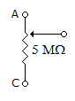
Answer: Option
Explanation:
A to C will act as short circuit, hence R = 0 if it open then R = ∞.
Quick links
Quantitative Aptitude
Verbal (English)
Reasoning
Programming
Interview
Placement Papers