Electronics and Communication Engineering - Electronic Devices and Circuits
Exercise : Electronic Devices and Circuits - Section 12
- Electronic Devices and Circuits - Section 14
- Electronic Devices and Circuits - Section 27
- Electronic Devices and Circuits - Section 26
- Electronic Devices and Circuits - Section 25
- Electronic Devices and Circuits - Section 24
- Electronic Devices and Circuits - Section 23
- Electronic Devices and Circuits - Section 22
- Electronic Devices and Circuits - Section 21
- Electronic Devices and Circuits - Section 20
- Electronic Devices and Circuits - Section 19
- Electronic Devices and Circuits - Section 18
- Electronic Devices and Circuits - Section 17
- Electronic Devices and Circuits - Section 16
- Electronic Devices and Circuits - Section 15
- Electronic Devices and Circuits - Section 1
- Electronic Devices and Circuits - Section 13
- Electronic Devices and Circuits - Section 12
- Electronic Devices and Circuits - Section 11
- Electronic Devices and Circuits - Section 10
- Electronic Devices and Circuits - Section 9
- Electronic Devices and Circuits - Section 8
- Electronic Devices and Circuits - Section 7
- Electronic Devices and Circuits - Section 6
- Electronic Devices and Circuits - Section 5
- Electronic Devices and Circuits - Section 4
- Electronic Devices and Circuits - Section 3
- Electronic Devices and Circuits - Section 2
6.
Power is drawn from a source at power factor 0.7. Pav = 300 watt. The reactive power is
Answer: Option
Explanation:
cos θ = 0.7  sin θ = 0.71
Pr =  VI sin θ = x 300 x 0.7 107 VA.
7.
Two capacitors each of capacitance C and breakdown voltage V are joined in series. The capacitance and breakdown voltage of the combination is
Answer: Option
Explanation:
Since the capacitors are in series, the total capacitance becomes 50%. Voltage across each is V.
8.
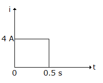
The current wave shown in figure is applied at t = 0 to a 0.1 F capacitor. At t = 1 s, the voltage across capacitor is
Answer: Option
Explanation:
Q = 4 x 0.5 = 2C and 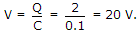
9.
A capacitor can be represented by a capacitance C in parallel with a resistance R. For a good capacitor, the resistance R should be
Answer: Option
Explanation:
Very high R will mean low dielectric loss.
10.
If a sheet of a mica is inserted between the plates of an air capacitor, the capacitance
Answer: Option
Explanation:
 For mica ∈r is more than that of air.
Quick links
Quantitative Aptitude
Verbal (English)
Reasoning
Programming
Interview
Placement Papers