Electronics and Communication Engineering - Electronic Devices and Circuits
Exercise : Electronic Devices and Circuits - Section 11
- Electronic Devices and Circuits - Section 14
- Electronic Devices and Circuits - Section 27
- Electronic Devices and Circuits - Section 26
- Electronic Devices and Circuits - Section 25
- Electronic Devices and Circuits - Section 24
- Electronic Devices and Circuits - Section 23
- Electronic Devices and Circuits - Section 22
- Electronic Devices and Circuits - Section 21
- Electronic Devices and Circuits - Section 20
- Electronic Devices and Circuits - Section 19
- Electronic Devices and Circuits - Section 18
- Electronic Devices and Circuits - Section 17
- Electronic Devices and Circuits - Section 16
- Electronic Devices and Circuits - Section 15
- Electronic Devices and Circuits - Section 1
- Electronic Devices and Circuits - Section 13
- Electronic Devices and Circuits - Section 12
- Electronic Devices and Circuits - Section 11
- Electronic Devices and Circuits - Section 10
- Electronic Devices and Circuits - Section 9
- Electronic Devices and Circuits - Section 8
- Electronic Devices and Circuits - Section 7
- Electronic Devices and Circuits - Section 6
- Electronic Devices and Circuits - Section 5
- Electronic Devices and Circuits - Section 4
- Electronic Devices and Circuits - Section 3
- Electronic Devices and Circuits - Section 2
6.
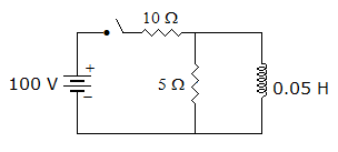
In the circuit of figure the switch is closed at t = 0, At t = 0+ this current through inductance is
Answer: Option
Explanation:
Current through an inductance cannot change instantaneously.
7.
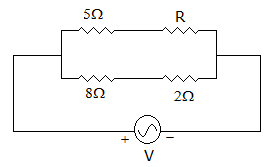
In the circuit of figure, the source supplies, 2.25 mA. The value of R must be
Answer: Option
Explanation:
The current through 8 ohm and 2 ohm resistances is  A or 1 mA.
Therefore, current through (5 + R) ohm is 1.25 mA. 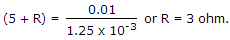
8.
The sum of positive real functions
Answer: Option
Explanation:
It is a property of positive real functions.
9.
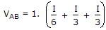
Twelve 1 Ω resistance are used as edges to form a cube. The resistance between two diagonally opposite corners of the cube is
Answer: Option
Explanation:
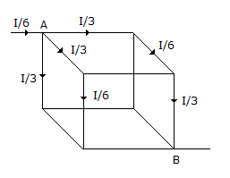
 .
.
10.
A parallel RLC circuit has ω0 = 106 and Q = 30, Given C = 30 pF, the value of R is
Answer: Option
Explanation:
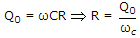
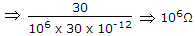 .
.
Quick links
Quantitative Aptitude
Verbal (English)
Reasoning
Programming
Interview
Placement Papers