Electronics and Communication Engineering - Electronic Devices and Circuits
Exercise : Electronic Devices and Circuits - Section 10
- Electronic Devices and Circuits - Section 14
- Electronic Devices and Circuits - Section 27
- Electronic Devices and Circuits - Section 26
- Electronic Devices and Circuits - Section 25
- Electronic Devices and Circuits - Section 24
- Electronic Devices and Circuits - Section 23
- Electronic Devices and Circuits - Section 22
- Electronic Devices and Circuits - Section 21
- Electronic Devices and Circuits - Section 20
- Electronic Devices and Circuits - Section 19
- Electronic Devices and Circuits - Section 18
- Electronic Devices and Circuits - Section 17
- Electronic Devices and Circuits - Section 16
- Electronic Devices and Circuits - Section 15
- Electronic Devices and Circuits - Section 1
- Electronic Devices and Circuits - Section 13
- Electronic Devices and Circuits - Section 12
- Electronic Devices and Circuits - Section 11
- Electronic Devices and Circuits - Section 10
- Electronic Devices and Circuits - Section 9
- Electronic Devices and Circuits - Section 8
- Electronic Devices and Circuits - Section 7
- Electronic Devices and Circuits - Section 6
- Electronic Devices and Circuits - Section 5
- Electronic Devices and Circuits - Section 4
- Electronic Devices and Circuits - Section 3
- Electronic Devices and Circuits - Section 2
36.
The pole of a reactive function
Answer: Option
Explanation:
A reactance function means that the network is composed of only L and C. Since there is no resistance, poles lie on jω axis only.
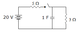
37.
In the circuit of figure the current through 3 Ω resistance at t = 0+ is
Answer: Option
Explanation:
The 3Ω resistance is short-circuited by capacitor at t = 0.
38.
Wave A starts its positive half cycle at ωt = 30° and wave B starts its positive half cycle at ωt = 75° then wave B is leading wave A by 45°.
Answer: Option
Explanation:
B is lagging A by 45°.
39.
Assertion (A): For networks in figure (1) and (2) sum of products of branch voltages and branch currents at any time is zero.
Reason (R): The networks in figure (1) and (2) are not the same structurally.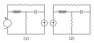
Answer: Option
Explanation:
A is statement of Tellegen's theorem while R is wrong.
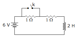
40.
In the circuit of figure the switch is open for a long time, At t = 0 the switch is closed. At t = 0+ the current supplied by battery is
Answer: Option
Explanation:
Inductance does not allow the current to change instantaneously.
Quick links
Quantitative Aptitude
Verbal (English)
Reasoning
Programming
Interview
Placement Papers