Electronics and Communication Engineering - Electronic Devices and Circuits
Exercise : Electronic Devices and Circuits - Section 7
- Electronic Devices and Circuits - Section 14
- Electronic Devices and Circuits - Section 27
- Electronic Devices and Circuits - Section 26
- Electronic Devices and Circuits - Section 25
- Electronic Devices and Circuits - Section 24
- Electronic Devices and Circuits - Section 23
- Electronic Devices and Circuits - Section 22
- Electronic Devices and Circuits - Section 21
- Electronic Devices and Circuits - Section 20
- Electronic Devices and Circuits - Section 19
- Electronic Devices and Circuits - Section 18
- Electronic Devices and Circuits - Section 17
- Electronic Devices and Circuits - Section 16
- Electronic Devices and Circuits - Section 15
- Electronic Devices and Circuits - Section 1
- Electronic Devices and Circuits - Section 13
- Electronic Devices and Circuits - Section 12
- Electronic Devices and Circuits - Section 11
- Electronic Devices and Circuits - Section 10
- Electronic Devices and Circuits - Section 9
- Electronic Devices and Circuits - Section 8
- Electronic Devices and Circuits - Section 7
- Electronic Devices and Circuits - Section 6
- Electronic Devices and Circuits - Section 5
- Electronic Devices and Circuits - Section 4
- Electronic Devices and Circuits - Section 3
- Electronic Devices and Circuits - Section 2
46.
In a linear circuit, the superposition principle can be applied to calculate the
Answer: Option
Explanation:
Apply KVL
(4 - I) 10 + 4 (9 - I) = 5 I
 I = 4A
P = I2.R 80 W.
47.
If A = 7 ∠15, A2 is
Answer: Option
Explanation:

48.
The colour coding of a resistors shows 100 K, ± 10%. When the resistance was measured with an ohmmeter, it read
Answer: Option
Explanation:
Ohmmeter measured 100 K ± 10/2 95 Ω.
49.
The output voltage of a charger is
Answer: Option
Explanation:
The charger has to supply current to battery for charging. This is possible only if voltage of charger is more than that of battery.
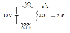
50.
The circuit in figure has reached steady values with switch open. If switch is closed at t = 0 the voltage across 2 μF capacitance at t = 0+ is
Answer: Option
Explanation:
At t = 0-, VC = 0 and voltage across a capacitor cannot change instantaneously.
Quick links
Quantitative Aptitude
Verbal (English)
Reasoning
Programming
Interview
Placement Papers