Electronics and Communication Engineering - Electronic Devices and Circuits
Exercise : Electronic Devices and Circuits - Section 4
- Electronic Devices and Circuits - Section 14
- Electronic Devices and Circuits - Section 27
- Electronic Devices and Circuits - Section 26
- Electronic Devices and Circuits - Section 25
- Electronic Devices and Circuits - Section 24
- Electronic Devices and Circuits - Section 23
- Electronic Devices and Circuits - Section 22
- Electronic Devices and Circuits - Section 21
- Electronic Devices and Circuits - Section 20
- Electronic Devices and Circuits - Section 19
- Electronic Devices and Circuits - Section 18
- Electronic Devices and Circuits - Section 17
- Electronic Devices and Circuits - Section 16
- Electronic Devices and Circuits - Section 15
- Electronic Devices and Circuits - Section 1
- Electronic Devices and Circuits - Section 13
- Electronic Devices and Circuits - Section 12
- Electronic Devices and Circuits - Section 11
- Electronic Devices and Circuits - Section 10
- Electronic Devices and Circuits - Section 9
- Electronic Devices and Circuits - Section 8
- Electronic Devices and Circuits - Section 7
- Electronic Devices and Circuits - Section 6
- Electronic Devices and Circuits - Section 5
- Electronic Devices and Circuits - Section 4
- Electronic Devices and Circuits - Section 3
- Electronic Devices and Circuits - Section 2
6.
In the circuit shown in the figure, the current supplied by the sinusoidal current source I is
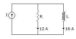
Answer: Option
Explanation:
I = (12)2 + (16)2 = 20 A.
7.
The frame of an electric motor is earthed through three earthing plates resistances 30 Ω, 20 Ω and 10 Ω respectively. During fault the energy dissipated by three plates are W1, W2 and W3. Then
Answer: Option
Explanation:
Energy dissipated by the plate with lowest resistance is maximum.
8.
If figure, power dissipated in 30Ω resistance will be maximum when value of R =
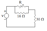
Answer: Option
Explanation:
When R = 0, circuit current =  and power dissipated =
  watts, which is the maximum possible value.
9.
In the following non-planar graph no.of independent loop equations are

Answer: Option
Explanation:
L = B - N + 1 = 12 - 8 + 1 = 5.
10.
Two voltages are 50 ∠0 V and 75 ∠ - 60° V. The sum of these voltages is
Answer: Option
Explanation:
50Ð0 = 50 + j 0.75∠-60° = 37.5 - j 64.95
Sum = (50 + 37.5) - j 64.95 = 87.5 - j 64.95 = 109∠-36.6°
Quick links
Quantitative Aptitude
Verbal (English)
Reasoning
Programming
Interview
Placement Papers