Electronics and Communication Engineering - Electronic Devices and Circuits
Exercise : Electronic Devices and Circuits - Section 3
- Electronic Devices and Circuits - Section 14
- Electronic Devices and Circuits - Section 27
- Electronic Devices and Circuits - Section 26
- Electronic Devices and Circuits - Section 25
- Electronic Devices and Circuits - Section 24
- Electronic Devices and Circuits - Section 23
- Electronic Devices and Circuits - Section 22
- Electronic Devices and Circuits - Section 21
- Electronic Devices and Circuits - Section 20
- Electronic Devices and Circuits - Section 19
- Electronic Devices and Circuits - Section 18
- Electronic Devices and Circuits - Section 17
- Electronic Devices and Circuits - Section 16
- Electronic Devices and Circuits - Section 15
- Electronic Devices and Circuits - Section 1
- Electronic Devices and Circuits - Section 13
- Electronic Devices and Circuits - Section 12
- Electronic Devices and Circuits - Section 11
- Electronic Devices and Circuits - Section 10
- Electronic Devices and Circuits - Section 9
- Electronic Devices and Circuits - Section 8
- Electronic Devices and Circuits - Section 7
- Electronic Devices and Circuits - Section 6
- Electronic Devices and Circuits - Section 5
- Electronic Devices and Circuits - Section 4
- Electronic Devices and Circuits - Section 3
- Electronic Devices and Circuits - Section 2
26.
Zinc oxide is a non-linear resistance.
Answer: Option
Explanation:
It is used in lightning arresters due to its non-linear resistance property.
27.
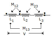
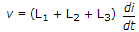
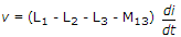
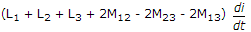
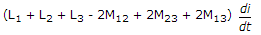
For the three coupled coils shown in figure, KVL equation is
Answer: Option
Explanation:
M12 is positive while M23 and M13 are negative because of dots shown in figure.
28.
Figure shows a dc circuit. The Thevenin's equivalent circuit at terminals a - b is
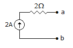
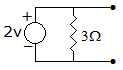
not feasible
Answer: Option
Explanation:
A current source with series resistance is not feasible.
29.
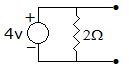
The dependent current source shown in given figure.
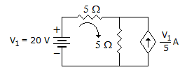
Answer: Option
Explanation:
P = I2.R  16 x 5 80 W,
Voltage source and current source both are in opposite direction.
30.
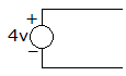
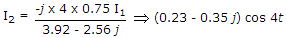
The current flowing through the resistance R in the circuit in the figure has the form 2 cos 4t, where R is
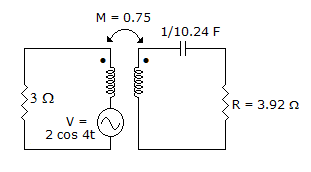
Answer: Option
Explanation:
Inductor is not given, hence ignoring the inductance. Let I1 and I2 are currents in the loop then
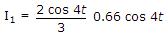
 .
.
Quick links
Quantitative Aptitude
Verbal (English)
Reasoning
Programming
Interview
Placement Papers