Electronics and Communication Engineering - Electronic Devices and Circuits
Exercise : Electronic Devices and Circuits - Section 3
- Electronic Devices and Circuits - Section 14
- Electronic Devices and Circuits - Section 27
- Electronic Devices and Circuits - Section 26
- Electronic Devices and Circuits - Section 25
- Electronic Devices and Circuits - Section 24
- Electronic Devices and Circuits - Section 23
- Electronic Devices and Circuits - Section 22
- Electronic Devices and Circuits - Section 21
- Electronic Devices and Circuits - Section 20
- Electronic Devices and Circuits - Section 19
- Electronic Devices and Circuits - Section 18
- Electronic Devices and Circuits - Section 17
- Electronic Devices and Circuits - Section 16
- Electronic Devices and Circuits - Section 15
- Electronic Devices and Circuits - Section 1
- Electronic Devices and Circuits - Section 13
- Electronic Devices and Circuits - Section 12
- Electronic Devices and Circuits - Section 11
- Electronic Devices and Circuits - Section 10
- Electronic Devices and Circuits - Section 9
- Electronic Devices and Circuits - Section 8
- Electronic Devices and Circuits - Section 7
- Electronic Devices and Circuits - Section 6
- Electronic Devices and Circuits - Section 5
- Electronic Devices and Circuits - Section 4
- Electronic Devices and Circuits - Section 3
- Electronic Devices and Circuits - Section 2
6.
A resistance coil has self inductance L, resistance R and capacitance C. The impedance across the coil is


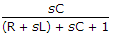
Answer: Option
Explanation:
The coil has R and L in series and C in parallel.
7.
In figure, the current iL at t = ∞ is
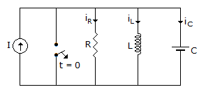
I
0


Answer: Option
Explanation:
At t = ∞, inductance behaves as short-circuit.
8.
When a lead acid cell is in fully charged condition the positive and negative plates are similar.
Answer: Option
Explanation:
They are similar in discharged condition.
9.
Two capacitors of 1 μF and 2 μF capacitance are connected in parallel across a 30 V dc battery. After the capacitors have been charged, the charges across the two capacitors will be
Answer: Option
Explanation:
Q1 = 1 x 10-6 x 30 = 30 μC, Q2 = 2 x 10-6 x 30 = 60 μC.
10.
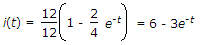
In figure, the battery has remained switched on for a long time. At t = 0 the switch is closed. The current i(t) is likely to be
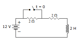
Answer: Option
Explanation:
Quick links
Quantitative Aptitude
Verbal (English)
Reasoning
Programming
Interview
Placement Papers