Electronics and Communication Engineering - Analog Electronics
Exercise : Analog Electronics - Section 3
- Analog Electronics - Section 11
- Analog Electronics - Section 21
- Analog Electronics - Section 20
- Analog Electronics - Section 19
- Analog Electronics - Section 18
- Analog Electronics - Section 17
- Analog Electronics - Section 16
- Analog Electronics - Section 15
- Analog Electronics - Section 14
- Analog Electronics - Section 13
- Analog Electronics - Section 12
- Analog Electronics - Section 1
- Analog Electronics - Section 10
- Analog Electronics - Section 9
- Analog Electronics - Section 8
- Analog Electronics - Section 7
- Analog Electronics - Section 6
- Analog Electronics - Section 5
- Analog Electronics - Section 4
- Analog Electronics - Section 3
- Analog Electronics - Section 2
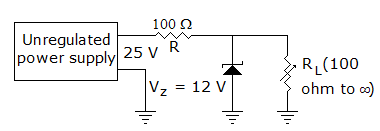
11.
In figure the zener current
Answer: Option
Explanation:
When IL = 0, Zener current = 130 mA, when IL = 120 mA, zener current (t = 10 mA).
12.
In a commercially available good power supply the voltage regulation is about
Answer: Option
Explanation:
A good power supply does not allow output voltage to vary by more than 1% .
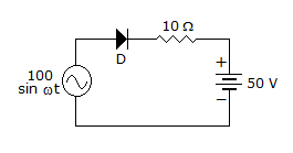
13.
In the circuit of figure the diode
Answer: Option
Explanation:
Diode will always be reverse biased.
14.
The most commonly used bias in BJT amplifier circuits is
Answer: Option
Explanation:
Voltage divider bias stabilizes IC.
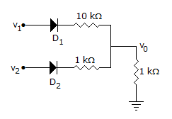
15.
In the circuit of figure, v1 = v2 = 10 V. Then
Answer: Option
Explanation:
Current in diode D2 will be more because resistance in series with D2 is less.
Quick links
Quantitative Aptitude
Verbal (English)
Reasoning
Programming
Interview
Placement Papers