Electronics and Communication Engineering - Analog Electronics
Exercise : Analog Electronics - Section 12
- Analog Electronics - Section 11
- Analog Electronics - Section 21
- Analog Electronics - Section 20
- Analog Electronics - Section 19
- Analog Electronics - Section 18
- Analog Electronics - Section 17
- Analog Electronics - Section 16
- Analog Electronics - Section 15
- Analog Electronics - Section 14
- Analog Electronics - Section 13
- Analog Electronics - Section 12
- Analog Electronics - Section 1
- Analog Electronics - Section 10
- Analog Electronics - Section 9
- Analog Electronics - Section 8
- Analog Electronics - Section 7
- Analog Electronics - Section 6
- Analog Electronics - Section 5
- Analog Electronics - Section 4
- Analog Electronics - Section 3
- Analog Electronics - Section 2
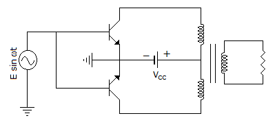
1.
In figure the collector to emitter breakdown voltage of the transistor (βVCEO) should be
2.
An amplifier signal is made up of just two frequencies 1000 Hz. The output signal consists of 500 Hz and 25000 Hz frequencies. This may be attributed to
3.
If input ac is 10 Vrms, then maximum voltage that will appear across the diode of a half wave rectifier with a capacitor I/P filter will be
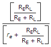
4.
In figure the voltage gain is
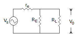

re

5.
One of the major applications of JFET is in
Quick links
Quantitative Aptitude
Verbal (English)
Reasoning
Programming
Interview
Placement Papers