Digital Electronics - MSI Logic Circuits - Discussion
Discussion Forum : MSI Logic Circuits - General Questions (Q.No. 11)
11.
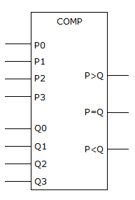
It is suspected that the comparator in the figure given below has a problem. The inputs are activated in the table shown below and the corresponding outputs noted. What is most likely wrong with the circuit?
For P0 – P3 = 1 and Q0 – Q3 = 0, P > Q = 1, P = Q = 1, P < Q = 0
For P0 – P3 = 0 and Q0 – Q3 = 1, P > Q = 0, P = Q = 1, P < Q = 1
For P0 – P3 = 1 and Q0 – Q3 = 1, P > Q = 0, P = Q = 1, P < Q = 0
Discussion:
Be the first person to comment on this question !
Post your comments here:
Quick links
Quantitative Aptitude
Verbal (English)
Reasoning
Programming
Interview
Placement Papers