Digital Electronics - MSI Logic Circuits
- MSI Logic Circuits - General Questions
- MSI Logic Circuits - True or False
- MSI Logic Circuits - Filling the Blanks
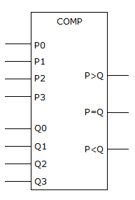
It is suspected that the comparator in the figure given below has a problem. The inputs are activated in the table shown below and the corresponding outputs noted. What is most likely wrong with the circuit?
For P0 – P3 = 1 and Q0 – Q3 = 0, P > Q = 1, P = Q = 1, P < Q = 0
For P0 – P3 = 0 and Q0 – Q3 = 1, P > Q = 0, P = Q = 1, P < Q = 1
For P0 – P3 = 1 and Q0 – Q3 = 1, P > Q = 0, P = Q = 1, P < Q = 0
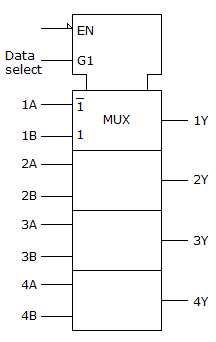
Which statement best describes the given figure, and what is the function of the terminal labeled EN?
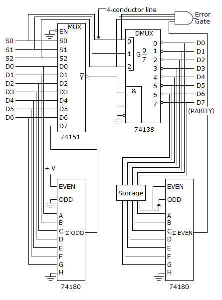
The data transmission system shown in below has a problem; the parity error output is always high. A logic analyzer is used to examine the system and shows that the DATA IN on the left matches the DATA OUT on right. What might be causing the problem?