Digital Electronics - MSI Logic Circuits

Exercise : MSI Logic Circuits - General Questions
26.
There appears to be a problem with a 7-segment display on a DMM sometimes skipping certain numbers. How would you test the display?
Remove the display unit and check each segment diode with an ohmmeter. Replace the defective segments.
Apply 5 V directly to each segment of the display and check for individual segment operation. Replace any segment that has voltage applied but is not lit.
Tie all of the segments together and connect to Vcc; the number 8 should appear on the display. Now check the display supply voltage to determine if the display is receiving the correct voltage.
Connect the DMM to a variable supply and very slowly increase the voltage, while observing for missing digits. Then check the segment voltage to determine whether the display or the display driver is bad.
Answer: Option
Explanation:
No answer description is available. Let's discuss.

27.
What is the purpose of a decoder's inputs?
To allow the decoder to respond to the inputs to activate the correct output gate.
To disable the decoder outputs so that all outputs will be inactive.
To disable the inputs and activate all outputs.
To allow the decoder to respond to the inputs to activate the correct output gate, and to disable the inputs and activate all outputs.
Answer: Option
Explanation:
No answer description is available. Let's discuss.

28.

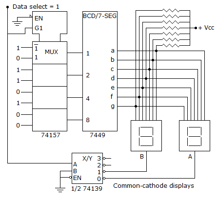
Refer to the display multiplexer given below. The MSD display is blank, while the LSD seems to be OK. The input and output lines to the 74157 and 7449 are checked with a scope and can be seen changing levels. The A input on the 74139 also changes; however, the 0 output on the 74139 is always LOW and the 1 output is always HIGH. The B and EN inputs on the 74139 are always LOW. What could cause the problem and what should be done to correct it?

The 74139 is defective; replace it.
The EN pin on the 74139 could have a bad connection; check the connection.
The 74139 is defective and must be replaced; or the EN pin on the 74139 could have a bad connection, which should be checked.
The MSD display is bad; replace it.
Answer: Option
Explanation:
No answer description is available. Let's discuss.

29.
The circuit in Figure 9-8 is defective; data is not appearing on the output lines. A check with the scope shows data pulses on the serial data line and multiplex control lines, S0–S2; no parity error is indicated. A further check with a logic probe indicates that Vcc and ground appear to be present. What might be wrong with the circuit?
The demultiplexer may be bad.
The parity checker is defective.
The parity generator may be bad.
The parity checker is defective, or the parity generator may be bad.
Answer: Option
Explanation:
No answer description is available. Let's discuss.

30.

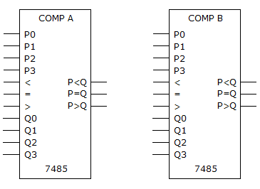
What must be done in the given figure in order to use two 7485 4-bit comparators to compare two 8-bit numbers?

The P < Q, P = Q, and P > Q outputs of COMP A must be connected to the same outputs of COMP B.
The P < Q, P = Q, and P > Q outputs of COMP A must be connected to the <, =, and > inputs of COMP B.
The = input of COMP A must be connected to Vcc, and the < and > inputs must be connected to ground.
The P < Q, P = Q, and P > Q outputs of COMP A must be connected to the <, =, and > inputs of COMP B, the = input of COMP A must be connected to Vcc, and the < and > inputs must be connected to ground.
Answer: Option
Explanation:
No answer description is available. Let's discuss.