Digital Electronics - MSI Logic Circuits
Why should I learn to solve Digital Electronics questions and answers section on "MSI Logic Circuits"?
Learn and practise solving Digital Electronics questions and answers section on "MSI Logic Circuits" to enhance your skills so that you can clear interviews, competitive examinations, and various entrance tests (CAT, GATE, GRE, MAT, bank exams, railway exams, etc.) with full confidence.
Where can I get the Digital Electronics questions and answers section on "MSI Logic Circuits"?
IndiaBIX provides you with numerous Digital Electronics questions and answers based on "MSI Logic Circuits" along with fully solved examples and detailed explanations that will be easy to understand.
Where can I get the Digital Electronics section on "MSI Logic Circuits" MCQ-type interview questions and answers (objective type, multiple choice)?
Here you can find multiple-choice Digital Electronics questions and answers based on "MSI Logic Circuits" for your placement interviews and competitive exams. Objective-type and true-or-false-type questions are given too.
How do I download the Digital Electronics questions and answers section on "MSI Logic Circuits" in PDF format?
You can download the Digital Electronics quiz questions and answers section on "MSI Logic Circuits" as PDF files or eBooks.
How do I solve Digital Electronics quiz problems based on "MSI Logic Circuits"?
You can easily solve Digital Electronics quiz problems based on "MSI Logic Circuits" by practising the given exercises, including shortcuts and tricks.
- MSI Logic Circuits - General Questions
- MSI Logic Circuits - True or False
- MSI Logic Circuits - Filling the Blanks
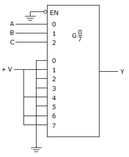
Refer to the figure given below. The logic function generator being implemented with the multiplexer in this circuit produces a constant LOW on the output. The ABC inputs are checked and appear to be pulsing; also, the 0–7 and EN inputs are checked with the scope and all appear to be at 0 V. A check with the DMM confirms that power is on. What is the problem, and what should be done to correct it?
Refer to the keyboard encoder in figure (a). Sometimes when the 5 key is pressed, the system attached to the keypad does not respond. The 5 input on the 74147 is monitored with a digital storage scope while repeatedly pressing the 5 key, and the waveform in figure (b) is obtained; the P above the trace indicates the points at which the technician pressed the key. What is most likely wrong with the circuit?

The BCD/DEC decoder shown in figure (a) is examined with a logic analyzer and the results are shown in the waveforms in figure (b). What, if anything, is wrong with the circuit?
