Digital Electronics - Logic Gates - Discussion
Discussion Forum : Logic Gates - Filling the Blanks (Q.No. 1)
1.
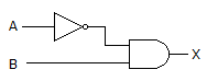
The gates in this figure are implemented using TTL logic. If the input of the inverter is open, and you apply logic pulses to point B, the output of the AND gate will be ________.
Discussion:
7 comments Page 1 of 1.
Gopi said:
1 decade ago
It is a wrong answer because 1*pulses gives the pulses output.
Sachin Dohre said:
1 decade ago
If A is open means undefined so output must be undefined level.
Nandi said:
1 decade ago
If A is open then o/p at inverter will be 0 (low) i.e. ground; So the o/p after and gate will be low only.
HARSHA said:
1 decade ago
If A is open it mean input to the inverter is 0 so the o/p will be 1. Which is applied to the AND gate input. So the o/p will be the pulses applied on B.
Appu said:
1 decade ago
Pulses is correct one.
Appu said:
1 decade ago
Answer is correct because. TTL is of negative logic so the input at inverter is open means it's high the output will be low so the and gate output is steady low.
Priya said:
9 years ago
Floating input of TTL is 1 always. So O/p of the NOT gate is I and B=1. But due to AND gate o/p becomes 0.
Post your comments here:
Quick links
Quantitative Aptitude
Verbal (English)
Reasoning
Programming
Interview
Placement Papers