Electronics and Communication Engineering - Networks Analysis and Synthesis - Discussion
Discussion Forum : Networks Analysis and Synthesis - Section 1 (Q.No. 13)
13.
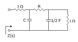
Z(c) for the network shown in the figure is 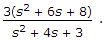 The value of C and R are, respectively
The value of C and R are, respectivelyDiscussion:
22 comments Page 1 of 3.
Prem said:
1 decade ago
Could you please provide explanation for this by formula?
Yasin said:
1 decade ago
For explanation refer to topic concept of network synthesis through long division method.
Puja said:
1 decade ago
Can you explain the answer?
James said:
1 decade ago
Can you explain with formula?
SATYAM said:
1 decade ago
Best explanation will be that at s=0 i.e at w=0 capacitor will be have as an open circuit.
So Z(s) = 8 at s = 0 i.e 4+R+8.
R = 4 ohm.
Of course you can solve it completely also.
So Z(s) = 8 at s = 0 i.e 4+R+8.
R = 4 ohm.
Of course you can solve it completely also.
(2)
Manikumar said:
1 decade ago
Add admittances of cap and res = (S/2)+1.
Then sum res = R+(2/S+2).
Add admittances = (CS)+(S+2/(R*(S+2)+2)).
Total = 3+(R*(S+2)+2))/(CS(R*(S+2)+2)) + (S+2));
Then sum res = R+(2/S+2).
Add admittances = (CS)+(S+2/(R*(S+2)+2)).
Total = 3+(R*(S+2)+2))/(CS(R*(S+2)+2)) + (S+2));
Vini said:
1 decade ago
Calculate impedance and compare?
Amit kumar said:
1 decade ago
Please explain this question.
Anusha sri said:
10 years ago
Please explain in detail.
Surya said:
10 years ago
@Satyam is correct.
Put s = 0, where the capacitor is open circuited, then find the equivalent impedance. After that put s = 0 in given z (s) that is get z (0). Equate this with the previous result and get R and in option, there is only one option with R = 4. So A is the right answer.
Put s = 0, where the capacitor is open circuited, then find the equivalent impedance. After that put s = 0 in given z (s) that is get z (0). Equate this with the previous result and get R and in option, there is only one option with R = 4. So A is the right answer.
Post your comments here:
Quick links
Quantitative Aptitude
Verbal (English)
Reasoning
Programming
Interview
Placement Papers