Electronics and Communication Engineering - Networks Analysis and Synthesis
Exercise : Networks Analysis and Synthesis - Section 24
- Networks Analysis and Synthesis - Section 14
- Networks Analysis and Synthesis - Section 27
- Networks Analysis and Synthesis - Section 26
- Networks Analysis and Synthesis - Section 25
- Networks Analysis and Synthesis - Section 24
- Networks Analysis and Synthesis - Section 23
- Networks Analysis and Synthesis - Section 22
- Networks Analysis and Synthesis - Section 21
- Networks Analysis and Synthesis - Section 20
- Networks Analysis and Synthesis - Section 19
- Networks Analysis and Synthesis - Section 18
- Networks Analysis and Synthesis - Section 17
- Networks Analysis and Synthesis - Section 16
- Networks Analysis and Synthesis - Section 15
- Networks Analysis and Synthesis - Section 1
- Networks Analysis and Synthesis - Section 13
- Networks Analysis and Synthesis - Section 12
- Networks Analysis and Synthesis - Section 11
- Networks Analysis and Synthesis - Section 10
- Networks Analysis and Synthesis - Section 9
- Networks Analysis and Synthesis - Section 8
- Networks Analysis and Synthesis - Section 7
- Networks Analysis and Synthesis - Section 6
- Networks Analysis and Synthesis - Section 5
- Networks Analysis and Synthesis - Section 4
- Networks Analysis and Synthesis - Section 3
- Networks Analysis and Synthesis - Section 2
36.
Assertion (A): When a square periodic wave is applied to an RC circuit, the voltage across capacitor is observed to be a triangular periodic wave.
Reason (R): The RC circuit works as integrator and its time constant is much larger than time period of input wave.
37.
Assertion (A): In a series resonant circuit current is maximum at resonance.
Reason (R): The inductive and capacitive reactances are equal.
38.
Laplace transform of a unit doublet U-2 (t) is
39.
A series RL circuit is excited by a voltage v(t) = Ve-at such that a = R/L. Then the circuit current is


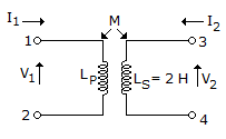
40.
In the transformer shown in the figure, the inductance measured across the terminal 1 and 2 was 4 H with open terminals 3 and 4. It was 3H when the terminals 3 and 4 were short circuited. The coefficient of coupling would be
Quick links
Quantitative Aptitude
Verbal (English)
Reasoning
Programming
Interview
Placement Papers