Electronics and Communication Engineering - Networks Analysis and Synthesis
Exercise : Networks Analysis and Synthesis - Section 6
- Networks Analysis and Synthesis - Section 14
- Networks Analysis and Synthesis - Section 27
- Networks Analysis and Synthesis - Section 26
- Networks Analysis and Synthesis - Section 25
- Networks Analysis and Synthesis - Section 24
- Networks Analysis and Synthesis - Section 23
- Networks Analysis and Synthesis - Section 22
- Networks Analysis and Synthesis - Section 21
- Networks Analysis and Synthesis - Section 20
- Networks Analysis and Synthesis - Section 19
- Networks Analysis and Synthesis - Section 18
- Networks Analysis and Synthesis - Section 17
- Networks Analysis and Synthesis - Section 16
- Networks Analysis and Synthesis - Section 15
- Networks Analysis and Synthesis - Section 1
- Networks Analysis and Synthesis - Section 13
- Networks Analysis and Synthesis - Section 12
- Networks Analysis and Synthesis - Section 11
- Networks Analysis and Synthesis - Section 10
- Networks Analysis and Synthesis - Section 9
- Networks Analysis and Synthesis - Section 8
- Networks Analysis and Synthesis - Section 7
- Networks Analysis and Synthesis - Section 6
- Networks Analysis and Synthesis - Section 5
- Networks Analysis and Synthesis - Section 4
- Networks Analysis and Synthesis - Section 3
- Networks Analysis and Synthesis - Section 2
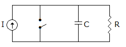
11.
The switch in figure is initially closed. At t = 0 the switch is opened. At t = 0+, the current through R is
I
0
Ie-t/RC

Answer: Option
Explanation:
At t = 0+ capacitor behaves as short-circuit.
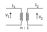
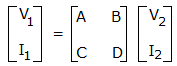
12.
The ABCD parameters of ideal n : 1 transformer shown in the figure are  . The value of X will be
. The value of X will beAnswer: Option
Explanation:
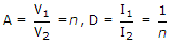 .
.
13.
If  , the network has
, the network hasAnswer: Option
Explanation:
 which means 1 H inductance and 1 F capacitor in parallel.
14.
The power dissipated in 4 Ω resistance in figure is
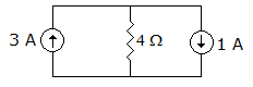
Answer: Option
Explanation:
Current through 4Ω resistance = 2 A.
15.
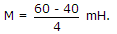
The total inductance of two coils is 60 mH in series aiding connection and 40 mH in series opposing connection. The mutual inductance between coils is
Answer: Option
Explanation:
Quick links
Quantitative Aptitude
Verbal (English)
Reasoning
Programming
Interview
Placement Papers